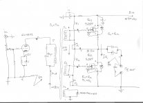
Nige and other members what do you think about this simple(simplified) complementary power bridge , is there Shade Fb or not?
ps, if moderator find that this post is off-topic it can be deleted , no hard feeling from me.")
It is kind of weird how on the forum here we have come up with a new name, "Schade Feedback," for a much older idea.
This is a follower output stage, so there is series applied voltage feedback. Otto Schade used series applied voltage feedback (applied with a special interstage transformer) to demonstrate the effects local feedback had on the characteristics of beam tubes in his paper on the 6L6. He could have used parallel-applied voltage feedback and still gotten similar results, but the driving circuit would have been pretty different.
So your question doesn't have a clear answer. We have been referring to parallel-applied voltage feedback on the forum here as "Schade feedback" even though that isn't even what Schade used. But it has similar effects to series-applied voltage feedback, except that the input impedance is lowered instead of raised.
Thanks for your input SpreadSpectrum !
And just one more question for you , did that sort of local voltage feedback achieved via R2&R3 converts power Lat-Fet`s basic pentode transfer characteristic closer to triode transfer characteristic ?, regardless to OPS lowered input impedance .
And just one more question for you , did that sort of local voltage feedback achieved via R2&R3 converts power Lat-Fet`s basic pentode transfer characteristic closer to triode transfer characteristic ?, regardless to OPS lowered input impedance .
Nige and other members what do you think about this simple(simplified) complementary power bridge , is there Shade Fb or not?
ps, if moderator find that this post is off-topic it can be deleted , no hard feeling from me.
yes, but signal source should be low Z
Thanks for your input SpreadSpectrum !
And just one more question for you , did that sort of local voltage feedback achieved via R2&R3 converts power Lat-Fet`s basic pentode transfer characteristic closer to triode transfer characteristic ?, regardless to OPS lowered input impedance .
Sorry, I was wrong in my circuit analysis above. I didn't notice you had p-channel on top and n-channel on bottom, so disregard what I said about this being series applied feedback.
This is parallel applied voltage feedback. Not the same as what Schade did in his paper but what is commonly called Schade on this forum. It will give the mosfet very triode-like characteristics. Input impedance will be low. This is the same kind of feedback that is in the classic inverting op-amp stage.
Thanks again SpreadSpectrum and hpeter !
Just to clarify my design target , that `Shaded` inverting A/B class OPS will work with R2&R3 values around 100K , bias pots will be with 10 time smaller values around 10K, just to allow me to get that specific bias point where power L-Fet`s works with IQ around zero tempco(150-200mA) , local degeneration or negative current feedback will be done with two 0,47-1R power resistors series connected on each L-Fet source ,yes I know that those two series connected source resistors will limit max DF , but I don`t hunt for max.DF anyway , 10 -15 DF will be just fine for my 16 ohm LS , and yes bipolar PSU will be around +/- 40VDC .
ps,for now I will be on stand by position since I don`t want to go off-topic to much
SS. How did this amp progress? I fancy it is very close to being what was requested.
Amp: KT88 push-pull shunt feedback output via p-channel fet
Amp: KT88 push-pull shunt feedback output via p-channel fet
One idea I had was like the Music Man amps that have cathode drive. We then could have pure shunt feedback from anode to g1. I suspect 220K is about OK for the feedback lower arm. The advantage is we keep it very simple. What we see is what we get. Alas it makes a valve verses transistor arguement more difficult if this example.

Putting a 220K resistor from plate to grid 1 on that Music Man schematic won't do much, just make the NPN bipolar collector voltage vary some. (although the 75K R from collector to base will then have some effect.) Really need a triode on the cascode bottom to get much N-Fdbk effects.
SS. How did this amp progress? I fancy it is very close to being what was requested.
Amp: KT88 push-pull shunt feedback output via p-channel fet
It works extremely well. Distortion was pretty low with 30% local feedback in the output stage, but Zout was 2.4 Ohms without any global feedback. That may be too high for some people's taste. The design could be easily altered with a higher gain first stage and a global feedback loop to further reduce distortion and Zout if that is desired.
I liked the simplicity that the p-channel fet feedback network driver offers. I guess the main drawback is the requirement for a negative rail and large negative bias on the gate of the fet. Not too big of a problem if you plan for it.
Thanks again SpreadSpectrum and hpeter !
Just to clarify my design target , that `Shaded` inverting A/B class OPS will work with R2&R3 values around 100K , bias pots will be with 10 time smaller values around 10K, just to allow me to get that specific bias point where power L-Fet`s works with IQ around zero tempco(150-200mA) , local degeneration or negative current feedback will be done with two 0,47-1R power resistors series connected on each L-Fet source ,yes I know that those two series connected source resistors will limit max DF , but I don`t hunt for max.DF anyway , 10 -15 DF will be just fine for my 16 ohm LS , and yes bipolar PSU will be around +/- 40VDC .
ps,for now I will be on stand by position since I don`t want to go off-topic to much
i´ve been thinking about schaded fets for long time.
this is one example, which is working but is bass shy (when i replace cap with transformer drive, it will be much wider BW and more stable gain per freq.)
350Hz..250kHz (-3dB)
http://peteslab.blogspot.sk/2017/04/stax-headphone-sic-amplifier-amberbridge.html
Putting a 220K resistor from plate to grid 1 on that Music Man schematic won't do much, just make the NPN bipolar collector voltage vary some. (although the 75K R from collector to base will then have some effect.) Really need a triode on the cascode bottom to get much N-Fdbk effects.
Love the photo of the Blackbird and Colleen even more so. I can't explain why a woman would, she took every oppertunity to see them at airshows. I lived next door to USAF Upper Heyford ( mostly F1-11 ), not sure we ever saw a Blackbird. B52's and most other things. When I say next door I mean the runway. It wasn't very noisy as we were sideways on to the aircraft. I could see the pilots and got a wave from time to time. F1-11 can come in slowly.
The 220K was in place of the usual grid leak and then whatever from plate to grid via a capacitor. Cathode drive would allow it to work without need of the driver Rp being a factor. To be honest although interesting it's a bit of a Frankenstein circuit.
One idea I had was like the Music Man amps that have cathode drive. We then could have pure shunt feedback from anode to g1. I suspect 220K is about OK for the feedback lower arm. The advantage is we keep it very simple. What we see is what we get. Alas it makes a valve verses transistor arguement more difficult if this example.
problem of this schematic : only the bjt are making gain.
tubes are just "crude series voltage regulators", protecting the bjts from hv
unfortunately, also many hybrid stax amps are made this way...

75k´s will not do much, since tubes are in tetrode mode.. wire them from anodes instead.
which it means, you can remove tubes, IF HIGH HV TRANSISTORS USED
I see that. I suspect the guitar world seeing valves used is more willing to buy. I am told Heavy Metal was a joke made by perhaps Jim Marshall saying if you put some lead in the case they will by a transistor amp. The very cheap Park amp made by them still has the house sound ( TDA2030? ). They say you have to read it backwards.

I am not saying this will work. Just to say how nice if it did. The feedback ( or feed forward ) paths can be whatever you want and can be same side or opposite. The idea is to manipulate the distortion and gain whilst keeping the signal path very simple. You might be forced to use EL84 which is no bad thing. Schade feedback should be possible. If the PNP side is removed it should be workable with a single resistor or CCS.
The simple op amp style biasing is my great like of this idea.
i´ve been thinking about schaded fets for long time.
this is one example, which is working but is bass shy (when i replace cap with transformer drive, it will be much wider BW and more stable gain per freq.)
350Hz..250kHz (-3dB)
http://peteslab.blogspot.sk/2017/04/stax-headphone-sic-amplifier-amberbridge.html
Zdravo Druze ! ( Hello Comrade ! )
Yes you are right that`Shaded` type of PP-OPS need driver unit with very low Z to get satisfying OL-BW , need to experiment with different driver tubes connected as CF , thinking about EL84 or even 6C19P for that position ,
maybe is interesting for you ,here`s one of my audio amp design(SET+SEPP) using driving transformer which also wait to be completed , all parts are here but no extra time for realisation
, those SJEP power J-Fet`s can be replaced with K1058 L-Fet`s , amp works very good in simulation with nice output THD spectrum , where Q1 is source follower and Q2 is `Shaded` drain follower .btw , I think that by Music Man RD50 amp 6L6GC tubes works in grounded grid pentode mode, where voltage gain and power gain is obtained both from cathode driving BJT`s and power tubes to , cathodes AC signal voltages are in phase with output anodes AC voltages resulting in zero Miller effect , that GG configuration is very good for driving power triodes , I think that obsolete 2SK213-2SK216 will also do the job very well as cathode drivers.
Attachments
hpeter
One very good option for that step-down driver transf. is Lundahl- LL1671 ,
anyway with that around 1W SET on the primary side you can explore various configuration on the secondary PP-SS side and to find what sound wise you like the most , on the secondary side it can be SEPP , Circlotron or PP complementary pair power bridge .
problem of this schematic : only the bjt are making gain.
tubes are just "crude series voltage regulators", protecting the bjts from hv
unfortunately, also many hybrid stax amps are made this way...
No. The Music Man arrangement is nothing else than a hybrid cascode - emitter grounded BJT and grid grounded power valve. Both components contribute to the total voltage gain.
Best regards!
Love the photo of the Blackbird and Colleen even more so. I can't explain why a woman would, she took every oppertunity to see them at airshows.
I liked the pilot story about a Blackbird over the North Sea that had an engine failure. Pilot radio'd in to some Norwegian airport for permission to land and they OK'd that, even though nothing was on the radar. Then this big long black thing lands on the runway and the pilot gets out with a space suit on. They thought the Aliens had landed and called security, so the pilot asked for a beer to cool things down. Too bad they were so expensive to run and got put out to pasture. Something else up there now.
Attachments

Last edited:
my bad.No. The Music Man arrangement is nothing else than a hybrid cascode - emitter grounded BJT and grid grounded power valve. Both components contribute to the total voltage gain.
Best regards!
since cascode is high Z out, i wonder what will happen on anodes, i think some untamed ringing or something
- Status
- This old topic is closed. If you want to reopen this topic, contact a moderator using the "Report Post" button.
- Home
- Amplifiers
- Tubes / Valves
- Schade Feedback In A Push Pull Differential Amplifier?