In AC terms it's not that great, I used a very similar circuit in the 1980s and 1990s except that the feedback was connected to the grid of the other tube in the LTP.
This isn't really an LTP give the very short tail resistance.
The basic topology when correctly implemented works extremely well and achieves good balance.
This isn't really an LTP give the very short tail resistance.
The basic topology when correctly implemented works extremely well and achieves good balance.
Excuse me but for me that's a load of some bovine you now whatI wrote this a long time ago.
I think it could help to understand (just a few french word but schematics are explicit enough IMO).
Equations Loyer pdf
Jacques

Undefined variables, double names, current that is not there ...
And the result is a (not very)LTP giving equal outputs

Mona
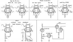
These equations are about the Loyez phase inverter.
Obviously, you don't understand how it works.
Only first stage plus global feedback provide the right shift and balance : this is the objet of the patent.
Second stage is not patented but is in the patent as to illustrate the phase inverter.
To make the balance less dependant of the global feedback, Loyez introduce a (imperfect) differential amplifier as a second stage plus 2 internal feedback loops.
I met several times Pierre Loyez in the 60s and had a lot of talks with him.
Jacques
No, although I can see why people often fall into this trap. The cap to ground from the second LTP grid in the conventional (e.g. Mullard) circuit has almost the same action as a coupling cap. It even introduces an LF rolloff. If you think of the LTP as purely having differential gain (which is almost true for a good circuit) then the two grids need to be at the same quiescent DC potential (so need a resistor between them) and need the AC signal applied to one of them. There are two options:petertub said:The ironic of this is that the cap that was eliminated don't carry any audio signal it's only grounding any AC !
1. feed one grid with AC via a cap, and connect the other to AC ground directly (this might need a negative supply for the cathode tail).
2. feed one grid with AC directly, and ground the other grid via a cap (this is the Mullard etc. circuit).
In both cases the pair of grids (with associated resistor(s)) and the cap form a series circuit from the AC signal source to ground. The only difference is the order, but for a perfect LTP the order does not matter because it has zero common-mode gain. So the cap is essentially a coupling cap in either position. Using DC coupling to the LTP does not eliminate an LF rolloff, as some people claim.
There is, of course, a third option: use two caps. An input coupling cap to one grid and an AC ground cap on the other grid (I think Leak used this?). The net effect is almost the same as using one cap.
For a real imperfect LTP with some common-mode gain the various circuits do different things at subsonic frequencies and that might affect LF loop stability, but in the audio band they all work the same way.
No, although I can see why people often fall into this trap. <snip>
+1
No, although I can see why people often fall into this trap.
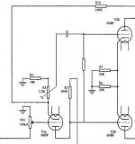
Agreed, the cap is always in the signal path, directly or indirectly (bypass cap on second grid (V1B in my schematic).
There are two options.....There is, of course, a third option: use two caps
There is a 4th option.....use no cap. Directly grounding the grid eliminates the possibility of nulling the offset which builds up in a directly coupled multi stage design. The 4th option is to hang an offset null pot across a low impedance, low noise bipolar power supply. Then connect the grid of the undriven tube (V1B) to the wiper of the pot. This leaves no cap in the signal path, but has two less that obvious disadvantages:
1) Power supply noise is directly injected into the amplifier input. Low noise supplies are essential, but when the offset pot is near center (the usual case) any hum and noise that is common to both supplies will be cancelled.
I usually derive the bipolar supplies with a bridge rectifier connected to a 120 - 0 - 120 volt isolation transformer like the Triad N-68X in a manner similar to most solid state amps. I use a CLC filter on each supply with the "L" being a common mode choke made from the primaries of any dual voltage (120 / 240 volt) power transformer. The load on each supply must be equal for hum to cancel if you use this "cheap choke".
I tried a low noise opamp configured as a DC source for the grid offset, but didn't hear or measure much improvement over the simple LM4041 circuit shown in my schematic. The bypass cap shown in my schematic was added for another reason and isn't always necessary but it was already in the board design before I sorted out #2.......
2) Any resistance between the second grid (V1B) and a low impedance virtual ground (offset voltage source) will form a pole with the miller capacitance of V1B which WILL roll off the high frequencies. It will also cause a phase imbalance in the LTP at high frequencies. I was losing a dB or two with a 100K pot and a 12AX7 tube before I figured this out. The resistor values shown in this scematic were my "best guess" values when I designed the board several years ago. They were based on what was in the octal version which ran a pair of 6SN7's. The roll off was not obvious with the lower gain design.
I have received a few questions about the NE-2 neon lamp. This is needed in some designs to avoid exceeding the H-K breakdown rating on cold power up. The tube will not be conducting so it's cathode will be at the negative supply rail voltage while the heater will be at ground or higher. It is a 1 pF cap when not conducting, but may be omitted if your negative rail doesn't exceed the breakdown rating of the tube.
I did successfully build a test amp using this circuit without the coupling caps or bias adjustments between V2 and the mosfets to directly drive the screen grids in a 3 stage DC coupled sweep tube amp design. Output tube current was set by a similar offset pot on its control grid. The amp did work and had no obvious caps in the signal path besides the usual power supply caps, but it required readjustment almost every day. I may explore this path again once I finish working on an Arduino compatible auto bias circuit......but this DOES require caps to keep the digital crud out of the audio!
Using a DC bias for the second LTP grid means that it has to track any variations in the DC level of the output from the previous stage applied to the first grid.
Not sure exactly what you are asking here, but using the schematic shown previously, I adjusted the offset pot for equal plate voltages on the second stage tube, and let the plates of the first stage fall where they may. Usually this was within a volt or so. If not I swapped tubes. After the amp was operational and burned in for a few days I tweaked the three pots (offset, first stage CCS current, and second stage CCS current) for best distortion profile.
The design evolved from the amp created here:
6L6GC AB2 Amp
I have used this driver board for everything from DHP's (307A's) to triode wired KT88's to big sweep tube amps. Once set up they don't require any more maintenance than any other tube amp. I am planning a triode wired 7403 amp with these boards sometime in the future.
center tapped plate inductors, called "balancing inductors",
Forcing the plates of the driver tube to a fixed DC voltage via a tapped inductor should help, but this was an experiment to see what would happen with 3 directly coupled stages. It showed me that it was a possibility, but it was running from my collection of old Ebay sourced power supplies of various age and condition. No real useful stability measurements were made to determine where the errors came from.
I could use a set of these for another project. I am experimenting with a push pull cathode follower output stage. This needs a big bunch of drive voltage which is best created with a typical push pull amp and an inductor like you describe. I have been using a P-P OPT with a very light load to minimize ringing. Note that the little blue and black open frame Edcor's will short out in a spectacular manner when attempting to make 1000 V P-P of drive from a 600 volt supply.
"Note that the little blue and black open frame Edcor's will short out in a spectacular manner when attempting to make 1000 V P-P of drive from a 600 volt supply."
You mean those little XSM 2.5 Watters?
W = VxV/R, 2.5 = VxV/15000, Vpk = 1.4 x 193.65 = 273 V
although the specifications readout seems to be stuck at 50V
We need to have Edcor wind some GXPP15 types with a CT'd primary only, for balancing inductors. (twice as much primary winding could fit on them without the secondary) Hopefully balanced resistances, or a couple of interleaves to equalize the resistances. Or just ask for 4 stacked (insulated) equal turn windings, can configure them externally.
Last edited:
Let me explain how i see it works.With illustations !These equations are about the Loyez phase inverter.
Obviously, you don't understand how it works. <snip>
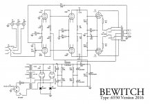
An out of balance concertina driving an out of balance LTP, compensating eachother.
You can adjust the balance with the feedback resistor but that changes the input level too.Adjustement are best made with Rc.
The bewitch amp can function with one triode less and an R-C coupling.
Mona
Attachments
Mona
In the Loyez phase inverter, you have to consider that the return of the feedback is on the cathode of V1a (the lower triode).
Triode V1b is in grill commun mode, the input is the cathode.
It makes a negative feedback on V1a and a positive feedback on V1b.
So amplitude at the output of V1a at the plate is reduced and output amplitude of V1b at the plate is increased.
Level of feedback is correct when both amplitudes are balanced.
As already said (not by me but by Loyez) V2 triodes are not involved in the process.
Unfortunately the patent is in french and may be difficult to read for some people, I agree.
Jacques
You mean those little XSM 2.5 Watters?
No, the OPT that I fried was originally bought for an experiment that was done along the lines of Pete Millett's Engineers Amp, but several years earlier.
I had purchased some little PC boards from a fellow diyAudio member that had 7 pin sockets connected to the green screw terminals that I use on my amp PC boards. I wired up 4 of these with a pair of 6AU6's and a pair of 6AQ5's, all configured as pentodes in a manner similar to the cascaded LTP's discussed here. The original intent was for a driver board, but I got a cheap OPT from Edcor to test it as a stand alone amp. It worked far better than I expected, and I decided to try it with better parts, but it never happened. The experiment got lost in the shuffle and I couldn't find the breadboard when I wanted to test it further.
Now, about 10 years and two house moves totaling 1200 miles, I open a box of junk, and I find it.......So I stole it's OPT for some small guitar amp experiments.
That's the OPT I fried a few weeks back. It is obviously an Edcor but has no stickers or markings, and my guess is probably an XPP10-8K or XPP10-10K, based on what I bought it for.
There could have been some damage to the OPT from living in a box of junk for years, but it did work fine in a 4 watt guitar amp on 170 volts, and as a stand alone amp running 4 small $1 tubes at the 15 watt level.....an experiment that will see further development.
OPT autopsy was inconclusive considering the fireball that ate it, but it looks like an arc from primary to secondary along the outer edge of the winding near one of the terminals for the primary. This might not have happened if I didn't have the secondary grounded, but I was experimenting with GNFB.
The only power supply that I have capable of producing 600 volts has a 1.7 Amp output capability and 1000 uF of capacitance across its output. This power supply makes little mistakes into BIG fireworks!
No, the feedback comes inverted by V1a on one side of the LTP and via V1b, not inverted, on the other side of the LTP.Making it NFB in both cases.Mona
In the Loyez phase inverter, you have to consider that the return of the feedback is on the cathode of V1a (the lower triode).
Triode V1b is in grill commun mode, the input is the cathode.
It makes a negative feedback on V1a and a positive feedback on V1b.
So amplitude at the output of V1a at the plate is reduced and output amplitude of V1b at the plate is increased.
Jacques
Mona
The feedback to the cathodes appears uninverted at both anodes of V1. However, as the two anodes have opposite signal polarities this is negative feedback for V1a and positive feedback for V1b.
Another way of looking at it is that the feedback has the same polarity as the signal already present at V1a cathode. It thus reduces the signal voltage across V1a g-k - so is negative feedback. It boost the signal voltage at V1a cathode, and so boosts the signal voltage at V1b cathode, thus boosting the signal voltage across V1b g-k - so is positive feedback. The net effect is negative feedback, because the reduction in V1A signal is greater than the boost in V1b signal.
Like most cathode feedback arrangements, this relies on common-mode distortion in V1 being small as the feedback cannot remove C-M distortion.
 DF96 is right, the FB goes to both cathodes, making one positive. But the extra voltage from the FB has to attenuated (smaller Rc) to restore the balance for the LTP, making the feedback to V1b is very small.
I think the grid signals to the second stage have to be equal or those outputs won't be equal. (180 deg. phase inputs. And equal value plate R's on the second stage)
V1a has very little effective input signal left after the neg. Fdbk at its cathode. So not much signal needed at V1b cathode to get the same (180 deg.) result.
----
"Like most cathode feedback arrangements, this relies on common-mode distortion in V1 being small as the feedback cannot remove C-M distortion."
I assume the CM dist. is just from the inherent tube dist. (and its loading) So a differential front end would be better in that respect.
-----
Needing a DC balance pot on the input cathodes (as posted earlier by jfetter, from the patent I think), that needs adjusting every month, does not put this circuit into favorable status.
Attachments
Last edited:
- Status
- This old topic is closed. If you want to reopen this topic, contact a moderator using the "Report Post" button.
- Home
- Amplifiers
- Tubes / Valves
- Can someone explain this confusing schematic?