I see the nonsense keeps flowing. CFA's with multiple mA flowing it the input stage have DC errors that make them fairly useless. Take say 250uA collector current and an optimal 1K feedback resistor at 26dB closed loop gain you are at the roll off of the constant GBW curve. Waly was correct.
Thanks, but there really isn't any nonsense here.
Multiple mA quiescent current for the input stage is the norm for all of the DIY discrete CFA power amplifier designs I have seen here any you can tailor the frequency compensation of any such design for an optimal value of Rf higher than 1k. Who cares about a couple of 10's of mV offset in a power amplifier design that you can trim out anyway?
There are also integrated CFA op-amps nowadays which essentially have complete op-amps followers in lieu of a basic diamond buffer for the input stage which deliver fractional-ohm inverting input impedance's.
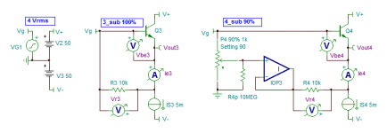
And for DIY you could easily knock up an Alexander-like switched-gain line stage or mic. amp which for all practical purposes achieves gain-bandwidth independence I demonstrated with the LTspice simulation of my prior post. I know, because I've done it.
OK. So that's a little-R e of 26mV/250uA = ~100 ohms, right? For a small signal analysis of a primitive "diamond buffer" I guess we have two re's effectively in parallel. Lets be generous and make the buffer output resistance 60 ohms.Take say 250uA collector current
I re-ran my simulation with the 1k Rf with a 60 ohm Zb. stepping the noise gain from 2 (6 dB) to 101 (40 dB) the closed loop bandwidth goes from 4.7 MHz to 750 kHz.
That's a 6.3:1 variation in closed loop bandwidth for a 50.5:1 variation in closed loop gain. Far from ideal but still a bit of a stretch to describe it to be "pure VFA behaviour".

And another thing just for curiosity's sake - when applying integrated CFA op-amps there is no reason to stick to the optimal specified value(s) of Rf if your bandwidth/distortion requirements don't require it. Suppose that you have an switched-gain instrumentation application that requires a 2 MHz bandwidth. Just pick a 20 MHz op-amp and use a ~10x higher Rf. Now you have much more room to play with Rg and the influence of Zo of the input buffer has been reduced by an order of magnitude.
Last edited:
Oh, and it's a composite CFA topology that inherits the noise performance of the integrated VFA utilized for the input buffer too.And for DIY you could easily knock up an Alexander-like switched-gain line stage or mic. amp which for all practical purposes achieves gain-bandwidth independence I demonstrated with the LTspice simulation of my prior post. I know, because I've done it.
.....when applying integrated CFA op-amps.....
What is available with "high voltage" ?
Last edited:
Do you believe that the open-loop circuitry of the standard CFA is more linear than that of a typical VFA? If it is, then that might allow for less gain overall to achieve a given THD level.
yes, it seems to be. In 1977 I put together a proof of concept CFA circuit using only 4 transistors. 40 db OPG and CLG of 20dB. 20db FB. at 22 v p to p output level it produced .0018% THD+N. Just started to move the needle of the HP339A. Much less at lower output 1-2v rms.
Today, my measuring limit using the lab standard ShibaSoku 725D is -160dBv. The HPA is similar topology and with excellent matching nd some trim of resistors, I get at or below the AP 2722 which is very good for a simple topology. It IS the topology that is responsible.
-Richard
Last edited:
What is available with "high voltage" ?
?? It was just some tangential technical CFA feedback trivia; I obviously wasn't talking about HV applications. I don't know; pick a manufactures website and run a parametric search.
Then, idle talk. Isn't this thread about power amplifiers ?
A final VFA/CFA comparison would be comparing power amplifiers using available op amp as front ends. Why re invent the wheel, playing op-amp designers ? Compare power amplifiers of same power, using the same output stage.
Everthing the same but the front end, CFA versus VFA.
A final VFA/CFA comparison would be comparing power amplifiers using available op amp as front ends. Why re invent the wheel, playing op-amp designers ? Compare power amplifiers of same power, using the same output stage.
Everthing the same but the front end, CFA versus VFA.
but I have seen 12 ohms or less in some recent devices iirc.
Yep. I'd like to be considered a layman reading through the discussion and trying to make sense of the arguments by putting some numbers to the claims and assertions. I hope that I've contributed something other than conceit and a 5th-graders punctuation on this point.
Even if I take as an example a really lousy incarnation of a CFA op-amp with a buffer Zout of 50 ohms or so, I still can't figure a justification for the hyperbolic generalization that CFA amplifiers in general posses "pure VFA"-like gain-bandwidth dependence when the Rf/Rg ratio is such that the resistance presented to the inverting input is essentially Rg; which basically translates to closed loop gains greater than 10.
Last edited:
Note to self:Then, idle talk.
Isn't this thread about power amplifiers ?
A final VFA/CFA comparison would be comparing power amplifiers using available op amp as front ends.
Why re invent the wheel, playing op-amp designers ?
Compare power amplifiers of same power, using the same output stage.
Everthing the same but the front end, CFA versus VFA.
Don't feed the troll.
What is available with "high voltage" ?
https://linearaudio.nl/sites/linearaudio.net/files/industry CFA table.pdf
Jan
It makes sense as either an ideal limiting case or as a first approximation. You normally want the open-loop transimpedance, transadmittance, voltage gain and current gain to be as high as possible to make the error terms as small as possible; let the transimpedance, transadmittance, voltage gain and current gain approach infinity and you get a nullor. If you are interested in the precise value of the error, you can't approximate it as zero of course.
You are right of course, Marcel. Assuming a zero error is a nice quick way to be able to design/analyze a feedback amp almost from the top of your head.
But these things have a tendence to 'start to live a life of their own' as we would say.
Thinking about the actual error magnitude (and phase) does increase one's understanding of the issues.
Jan
Just something further in this context which was that of the brouhaha which resulted in one member packing his bags and leaving (recall that the typical 26dB gain figure cited was in reference to audio power amplifiers - NOT integrated op-amps with 250uA quiescent input stage current as suggested by scott wurcer.)Multiple mA quiescent current for the input stage is the norm for all of the DIY discrete CFA power amplifier designs I have seen here any you can tailor the frequency compensation of any such design for an optimal value of Rf higher than 1k. Who cares about a couple of 10's of mV offset in a power amplifier design that you can trim out anyway?
I half feel like a dork for getting drawn into this nonsense. The argument over gain-bandwidth dependence is practically moot anyway, as virtually all such designs operate at a single fix gain. If, for whatever reason, right or wrong, you're an advocate for building "current feedback" power amplifiers, the theoretical gain-bandwidth (in)dependence of your implementation is neither here nor there. You choose a suitable fixed gain for your amplifier and frequency compensate for that specific gain and that is it.
Last edited:
Not much there in terms of "high voltage", but in the context of current feedback audio power amplifiers utilizing an integrated op-amp for the input stage, the only such example that springs to mind is the "Alexander amplifier". In that design the power supply rails of the op-amp are cascoded with bipolar junction transistors; a high supply voltage op-amp isn't required.
Not much there in terms of "high voltage", but in the context of current feedback audio power amplifiers utilizing an integrated op-amp for the input stage, the only such example that springs to mind is the "Alexander amplifier". In that design the power supply rails of the op-amp are cascoded with bipolar junction transistors; a high supply voltage op-amp isn't required.
Yes the Alexander is a nice example, although probably not at the current state of the art.
Another option would be an output stage with a small gain of say 3x or 5x. That has been successful also.
BTW The discussion about constant GBW or BW was not specifically in the context of power amps but more in the context of differences between CFA and VFA. You are of course right that once you fix the design parameters it is largely moot.
Jan
Last edited:
Yeah, generally so, but it specifically was in the instance of the final spat between Wally and Bonsai, which immediately followed Wally's reply to me in which he pontificated about Rg||Rf=~Rg and 26dB-gain power amplifiers and all that. Around abouts here:BTW The discussion about constant GBW or BW was not specifically in the context of power amps but more in the context of differences between CFA and VFA. You are of course right that once you fix the design parameters it is largely moot.
http://www.diyaudio.com/forums/soli...dback-amplifiers-semantic-35.html#post5163563
Yeah, generally so, but it specifically was in the instance of the final spat between Wally and Bonsai, which immediately followed Wally's reply to me in which he pontificated about Rg||Rf=~Rg and 26dB-gain power amplifiers and all that. Around abouts here:
http://www.diyaudio.com/forums/soli...dback-amplifiers-semantic-35.html#post5163563
OK, I see. But we have no difference of opinion I believe. And even if we had, so what

Jan
Is it time to start at least partially summing up?
There seem to be at least two discussion threads here. One is about nomenclature; the other about the operational characteristics of certain IC’s.
On the nomenclature topic, we might consider the feedback topologies of complete amplifier circuits as well as some characteristics of the amplifiers at the heart of these networks. These are really two separate issues.
I think we all recognize that there are four feedback topologies, sometimes referred to as series derived, series applied; series derived, shunt applied; shunt derived, series applied; and shunt derived, shunt applied. Whatever the historical precedent, the term CFA if applied here is ambiguous; does the “F” refer to derived or applied feedback or both? It is not inherently obvious. For this reason, we should shun its use to describe a feedback topology.
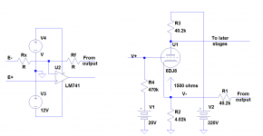
The characteristics of the amps at the heart of any of these four topologies are independent of those topologies. The amp could be like an old familiar friend with a traditional input stage such as the hoary LM741, or like a single triode whose cathode is the inverting input (see the schematic below.) For the ‘741, we would expect the inverting input impedance Z- to be greater than Rf || Rx and in such cases, we would say that voltage feedback predominates. But for the triode in the schematic below, the inverting input impedance is less than R1 || R2, and here, we would say that current feedback predominates. Why? Z- sees a feedback network whose Thevenin equivalent is a voltage source V in series with a resistance R. If Z- < R, a simple calculation shows that it is more accurate to say that a current V/R flows through Z than that Z sees a voltage source V. The situation is reversed if Z- > R.
Should amps fall into one of two different classes named CFA and VFA? Don’t hold your breath; I’m not going to argue for or against. But at least we can see a reason for choosing these terms to describe certain feedback network ( not feedback network topology! ) and inverting input impedance combinations.
It should be clear that amplifier / feedback network combinations which “see” either predominantly voltage or predominantly current feedback could be used in networks of any of the four feedback topology types. These two matters are independent of one another, unlike what was claimed in a certain (in)famous article.
There seem to be at least two discussion threads here. One is about nomenclature; the other about the operational characteristics of certain IC’s.
On the nomenclature topic, we might consider the feedback topologies of complete amplifier circuits as well as some characteristics of the amplifiers at the heart of these networks. These are really two separate issues.
I think we all recognize that there are four feedback topologies, sometimes referred to as series derived, series applied; series derived, shunt applied; shunt derived, series applied; and shunt derived, shunt applied. Whatever the historical precedent, the term CFA if applied here is ambiguous; does the “F” refer to derived or applied feedback or both? It is not inherently obvious. For this reason, we should shun its use to describe a feedback topology.
The characteristics of the amps at the heart of any of these four topologies are independent of those topologies. The amp could be like an old familiar friend with a traditional input stage such as the hoary LM741, or like a single triode whose cathode is the inverting input (see the schematic below.) For the ‘741, we would expect the inverting input impedance Z- to be greater than Rf || Rx and in such cases, we would say that voltage feedback predominates. But for the triode in the schematic below, the inverting input impedance is less than R1 || R2, and here, we would say that current feedback predominates. Why? Z- sees a feedback network whose Thevenin equivalent is a voltage source V in series with a resistance R. If Z- < R, a simple calculation shows that it is more accurate to say that a current V/R flows through Z than that Z sees a voltage source V. The situation is reversed if Z- > R.
Should amps fall into one of two different classes named CFA and VFA? Don’t hold your breath; I’m not going to argue for or against. But at least we can see a reason for choosing these terms to describe certain feedback network ( not feedback network topology! ) and inverting input impedance combinations.
It should be clear that amplifier / feedback network combinations which “see” either predominantly voltage or predominantly current feedback could be used in networks of any of the four feedback topology types. These two matters are independent of one another, unlike what was claimed in a certain (in)famous article.
Attachments
Is it time to start at least partially summing up?
Again?
Don’t hold your breath;
- Home
- Amplifiers
- Solid State
- Current Feedback Amplifiers, not only a semantic problem?