Hello All
Some years ago i built a SE amp based on UCL 82 with a lot of much appreciated support from here ! thanks again to all the people here
i just have very basic knowledge of electronics but that doesnt discourage me from diving into building a simple amp now and then.
i have come by some ECL86 tubes. I wish to build a good sounding SE amp which has good mid tones and sound kind of live.
I have an OPT that was taken off a german radio with EL84 SE. the opt is not small its at least 75 by 70 mm and had worked well with the UCL 82. My PS is already built and delivers 250dc thru a solid state rectifier then filtered with 100uf - 100 ohm - 100uf
Please suggest me a schematic that has actually been built and works well for ECL86. SE in pentode mode.
I would also like to see a wiring diagram for signal from my cellphone ( moto G3) to grid. i had issues earlier with floating signal or whatever that is... which gave me muffled sound output or distortion because of gain being too high or something. also please suggest a good grounding scheme.
Anxiously awaiting your inputs!
Warm regards
Amit
I have built the Mullard 3W variation that is described at page 35 of the book "HiFi amplifier Circuits" by E. Rodenhuis and published in the Philips technical library (google for the pdf). The topology is obviously the same but the working point is slightly different. The RC network in the global feedback loop should be adjusted for the specific output transformer. Output is rated 3W over 60Hz-40KHz range with the Philips AD9057 transformer. I used a similarly sized transformer with ultralinear tap, and I like the results better than the original circuit. I also added a 1H choke on the B+ to remove the faint residual hum. There is a obvious typo in the component list, the cathode resistor on the output pentode is the parallel of a 270 and 470 ohm resistors, not 270 and 470k
update on circuit i built
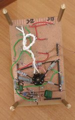
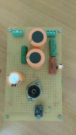
oK .. thanks for the suggestions for schematics. for my first circuit i put togetehr a simple one. Im just a small time tinkerer with little knowldege of electronics but i try to soak in and move forward. attached is the schematic that i built. i have two problems
1. very loud buzz when i put the input 3.5mm jack into the amp board( its actually point to point wiring on a general purpose board)
2. when i put the other end of the aux lead into my cellphone ...hum stops competely.
3. when i play music is gets really loud if i push it up to the last 30%.
4. but in the music passages where there low musical notes..like the begining of the song... i hear very bad distortions..entires notes dissapearing. ..like the sound wave got clipped or something. when the song is in its loud and normal parts i cant hear the distortion much at all..
5. if i put my finger tip to the end of the aux lead with the other into the amp..it gives me a high pitched whine.... there a loud buzz still when i remove my finger,
6.i have grounded the chassis on which the OPT and PT are fixed.
7. I would like to know how to kill this buzz... i think its some ground issue but how do i go about fixing it.? please suggest.
Thank you in advance
Amit
Attachments
The buzz you hear is there because the tube amplifier has a high impedence, therefore is very sensitive to any stray field. If the noise goes away when you connect the source (a low impedence circuit), that's fine and normal. If you really want to get rid of the buzzing noise, connect a 10K resistor on the input jack terminals, between signal input and ground. This is the input impedence on many portable speakers.
The distortion at low volume may be a issue of the source. Either the music is a mp3 with high compression, or the digital volume control of your phone is chopping away at the signal to attenuate it. You may try a uncompressed source (such as an old fashioned CD player) and/or add a volume potentiometer at the input of the amplifier to attenuate the signal and set the phone at maximum volume.
EDIT:
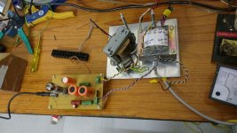
The tube radio output transformer you have recovered is a nice one, you should get a good sound. But i don't see the connection between the negative lead of the output transformer secondary and the ground. It is really needed with vintage transformers such as these. They use paper insulation, there may be a short between the primary and the secondary winding, and the ground connection will ensure a safe path towards ground for the fault current. You should really add a fuse in series with the secondary winding of the HT transformer. Without the fuse, any minor mistake that will short the HT may destroy your output transformer or the ECL86.
The distortion at low volume may be a issue of the source. Either the music is a mp3 with high compression, or the digital volume control of your phone is chopping away at the signal to attenuate it. You may try a uncompressed source (such as an old fashioned CD player) and/or add a volume potentiometer at the input of the amplifier to attenuate the signal and set the phone at maximum volume.
EDIT:
The tube radio output transformer you have recovered is a nice one, you should get a good sound. But i don't see the connection between the negative lead of the output transformer secondary and the ground. It is really needed with vintage transformers such as these. They use paper insulation, there may be a short between the primary and the secondary winding, and the ground connection will ensure a safe path towards ground for the fault current. You should really add a fuse in series with the secondary winding of the HT transformer. Without the fuse, any minor mistake that will short the HT may destroy your output transformer or the ECL86.
Last edited:
Hello Pcan
Thanks for your suggestions. i will try the 10 and the volume pot. i hop its not something called blocking... i will let you know what happened.
the amp is loud and music feels dymanic but not so clean. its the cutting of notes .... where can i send a video file so you guys can have a listen?
BR
Amit
Maybe you will like triode mode more (it does have less distortion). Desolder the HT lead of the 1K screen resistor and connect it to the anode. You basically will have a 1K resistor between pin 6 and pin 3. The sound will chang, and the volume will be lower.
By the way, tube radio transformers are almost always optimized for a 5 ohm speaker. If your speaker is 8 ohms, distortion will increase slightly.
By the way, tube radio transformers are almost always optimized for a 5 ohm speaker. If your speaker is 8 ohms, distortion will increase slightly.
the secondary of the OPT are two wires..black and red that go to my speaker. (which is 8ohm full range whizzer cone speaker). yes i can add a fuse...where shall i add it? and which of the two speaker wires( red or black) should i ground to the chassis? or does it go to the circuit ground? at present my circuit ground is not connected to chassis ground.
BR
Amit
BR
Amit
yes im combining the two channels into one via the 2resistors... yes i hear the cutting out sound.its terrible..when i can notice it...i had done something same years ago but no problems then...or have i wired it wrong.? each channel goes thru 10k resistors before joining together and then to the coupling cap
Last edited:
If global feedback is not implemented, such as in this circuit, it does not matter which output transformer secondary wire goes to ground. You may ground the black one, this is the standard color for the grounded terminal. The purpose is to short to ground the b+ if the transformer insulation fails. It should therefore be connected to circuit ground in your amp. I usually put the fuse in series with one of the power transformer HT secondary wires. The purpose of this fuse is to open the HT supply circuit should any short to ground happens.
- Status
- This old topic is closed. If you want to reopen this topic, contact a moderator using the "Report Post" button.
- Home
- Amplifiers
- Tubes / Valves
- ECL86 SE amp- help