This is my first attempted use of LTSpice, and also I'm *very* new with electronics in general.
I'm not sure if this post should be in the tools section, or the tube section, but here goes...
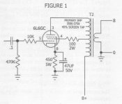
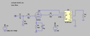
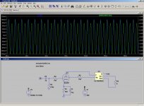
I have tried to copy a simple schematic to help me learn how the components work together, but things do not seem right - I'm not sure if it's the schematic or an error on my part.
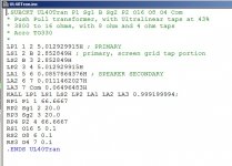
The circuit is for the output stage of an SE amp with UL tap. I used the speadsheet from this post: http://www.diyaudio.com/forums/tubes-valves/68767-spice-model-ul-output-transformer-post808769.html to (hopefully) find an appropriate transformer. The model is meant for PP but I'm not using the second tube tap (that could be one of the issues!).
First of all, the tube grid is supposed to be negative. Supplying a negative offset at IN doesn't work because of the cap at C2.
Measuring the difference between the grid voltage and the cathode bias shows a negative at all times, so maybe it doesn't matter that the grid itself isn't negative in this case?
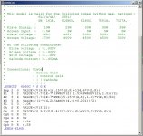
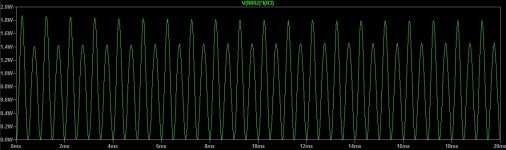
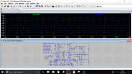
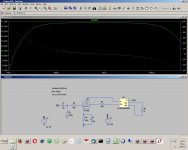
The output power at R3 is shown below, and obviously has troubles. Raising the voltage IN shows signs of clipping in the output voltage (not pictured), even though the voltage needs to increased to about 18v to get to somewhere near the expected output power (10W in this case).
I'm completely lost at to whether the issue is with the grid voltage (in which case I don't know how to fix it - I've tried adding a negative voltage to R2 instead of ground but LTSpice doesn't seem to like that, unless I'm doing it wrong), the transformer model, or (doubtfully) the schematic.
Please help me spot the problem!
I'm not sure if this post should be in the tools section, or the tube section, but here goes...
I have tried to copy a simple schematic to help me learn how the components work together, but things do not seem right - I'm not sure if it's the schematic or an error on my part.
The circuit is for the output stage of an SE amp with UL tap. I used the speadsheet from this post: http://www.diyaudio.com/forums/tubes-valves/68767-spice-model-ul-output-transformer-post808769.html to (hopefully) find an appropriate transformer. The model is meant for PP but I'm not using the second tube tap (that could be one of the issues!).
First of all, the tube grid is supposed to be negative. Supplying a negative offset at IN doesn't work because of the cap at C2.
Measuring the difference between the grid voltage and the cathode bias shows a negative at all times, so maybe it doesn't matter that the grid itself isn't negative in this case?
The output power at R3 is shown below, and obviously has troubles. Raising the voltage IN shows signs of clipping in the output voltage (not pictured), even though the voltage needs to increased to about 18v to get to somewhere near the expected output power (10W in this case).
I'm completely lost at to whether the issue is with the grid voltage (in which case I don't know how to fix it - I've tried adding a negative voltage to R2 instead of ground but LTSpice doesn't seem to like that, unless I'm doing it wrong), the transformer model, or (doubtfully) the schematic.
Please help me spot the problem!
Attachments
The grid will be negative with respect to the cathode i.e. the grid is always zero but the cathode will be some positive value depending on how hard it is conducting (determined by the cathode resistor). So if the cathode is plus 20 volts then you have effectively a negative 20 volts grid bias.
The grid will be negative with respect to the cathode i.e. the grid is always zero but the cathode will be some positive value depending on how hard it is conducting (determined by the cathode resistor). So if the cathode is plus 20 volts then you have effectively a negative 20 volts grid bias.
Yes, when checking the voltage difference it showed a negative grid compared to the cathode - but the grid itself (compared to 0v) was going positive. I wasn't sure if this was allowed; the model I copied says 0 to -60v?
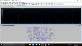
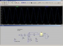
I found a newer version of that spreadsheet and it had a SE UL tran model - apart from the fact that the tube is expecting a transformer impedance of 3500 - 3750 and the nearest available in the calc was 5000.
Using this, it's not clipping the voltage any more at 18v, but there's still the bounce in the power output - although I've now noticed the bounce coincides with the positive/negative swing. Is this normal?
Using this, it's not clipping the voltage any more at 18v, but there's still the bounce in the power output - although I've now noticed the bounce coincides with the positive/negative swing. Is this normal?
Attachments
Another question (this time definitely LTSpice related!)...
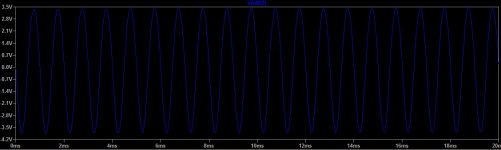
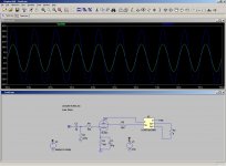
If I display the IN voltage and the voltage after the transformer at the same time, they both appear on the same scale but are of course completely different values. Is there a way to alter the scale for one set of data to enable the shape of the waveforms to be compared (before/after)?
Or this there a more correct way to achieve the same thing?
It is usual in valves. The gris is decoupled via a capacitor where it loses DC component, so grid floats on 0VDC, but as the cathode is +20V (Equal to say grid in negative respeto to cathode in 20V), then no grid current flows until peak grid voltage is +19V.Yes, when checking the voltage difference it showed a negative grid compared to the cathode - but the grid itself (compared to 0v) was going positive. I wasn't sure if this was allowed; the model I copied says 0 to -60v?
I'm new to spice myself but the transformer model looks wrong to me. You are using only half of the primary and the inductance of the whole primary looks low. Search for Robert Mclean's Transformer Models Rev4.xls on this site. You can use that to get a good model of an se ul transformer.
It was an old version of Robert's spreadsheet I found initially, which didn't help with the Spice model - the only one in that thread was for the PP UL, which I was trying to use.
I found the new one (which does the model for you) and got a SE UL model (but the closest impedance isn't that close) as per post #8.")
I found the new one (which does the model for you) and got a SE UL model (but the closest impedance isn't that close) as per post #8.
Ah! I didn't see the first tab - I don't think it was there on the first version of the spreadsheet. Thanks for that.
With a bit of scale twiddling, it looks as though the distortion that I first thought was IM is more like 2nd harmonic; which of course is what you'd expect on an SE design.
With a bit of scale twiddling, it looks as though the distortion that I first thought was IM is more like 2nd harmonic; which of course is what you'd expect on an SE design.
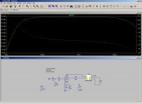
Another weird one - trying to match the wave patterns, there's a much larger difference in the gain (at 1khz) at a 6 ohm load (8 ohm tap) than at 8 ohms, and yet this is not visible if a frequency response sweep is done.
Attachments
- Status
- This old topic is closed. If you want to reopen this topic, contact a moderator using the "Report Post" button.
- Home
- Design & Build
- Software Tools
- Help with LTSpice... or something else?