Would you be willing to say what you see for a single tone, and under what conditions (say, power level, etc.)?
I ask because people often do a lot of listening at low levels. So distortion at various power levels would be of interest.
Also, there are also some people who seem to think that distortion (both linear and nonlinear) may be more noticeable when it is dynamic, changing with level, frequency, and whatever else there may be, perhaps time history for filters that may ring, or pre-ring, as the case may be.
yes, and I would test at 10-20W output... a near max average power for most home systems.
MLSSA water fall plot of an RIAA circuit is interesting also.
THx-RNMarsh
Last edited:
@ Bob, your article is a very good read.
I am concerned about the voltage levels discussed
on pages 10, 11, and 12; keeping in mind that should
I do the test the method Richard describes, I'll just
describe it the way Jimmy Dean does, "The Whole Hog"
method.
That being said, trying to place a signal through my preamp
at 5Volts going through a 35WPC Tube amp, to a pair of
Klipsch Cornwalls won't work too well.
I've got the system dialed in finally and it's sounding very good.
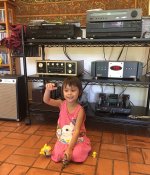
OLD Marantz CD 63SE, to tape input of Audio Research SP-3A1, to
a Series II Dynaco Stero 70 amp to Klipsch Cornwall speakers.
The electronics are filtered through an HTTPS 7000 MKII.
I put in a NOS match set of sylvania 6GH8As and NOS quad of UK EL34s.
With KD Lang's Ingenue...it is just funominal (sp).
I've got to find my Joan Baez and Patricia Barber live in Chicago doing
the Sonny and Cher tune, the beat goes on.
So what should I shoot for output of the MIM?
100 mV?
50 mV?
I can use an old calibrated mic to pic up the resulting tones from
the speakers....@ 1 meter on axis.
For what should I look and how to capture it?
I can feed it into the shibsoku 725D for analysis.
with and without filtering.
I can set up the main output tones with any kind of filter
that I need prior to feeding the pre amp.
Here is a pic of the system, Tiffany had to bring her toys and play.
Cheers,
I can wheel in my Measurement rack to the large room. It and it's filters
and tools and scope are mounted on one of those food service racks. To that
is doable too.
I am concerned about the voltage levels discussed
on pages 10, 11, and 12; keeping in mind that should
I do the test the method Richard describes, I'll just
describe it the way Jimmy Dean does, "The Whole Hog"
method.
That being said, trying to place a signal through my preamp
at 5Volts going through a 35WPC Tube amp, to a pair of
Klipsch Cornwalls won't work too well.
I've got the system dialed in finally and it's sounding very good.
OLD Marantz CD 63SE, to tape input of Audio Research SP-3A1, to
a Series II Dynaco Stero 70 amp to Klipsch Cornwall speakers.
The electronics are filtered through an HTTPS 7000 MKII.
I put in a NOS match set of sylvania 6GH8As and NOS quad of UK EL34s.
With KD Lang's Ingenue...it is just funominal (sp).
I've got to find my Joan Baez and Patricia Barber live in Chicago doing
the Sonny and Cher tune, the beat goes on.
So what should I shoot for output of the MIM?
100 mV?
50 mV?
I can use an old calibrated mic to pic up the resulting tones from
the speakers....@ 1 meter on axis.
For what should I look and how to capture it?
I can feed it into the shibsoku 725D for analysis.
with and without filtering.
I can set up the main output tones with any kind of filter
that I need prior to feeding the pre amp.
Here is a pic of the system, Tiffany had to bring her toys and play.
Cheers,
I can wheel in my Measurement rack to the large room. It and it's filters
and tools and scope are mounted on one of those food service racks. To that
is doable too.
Attachments
Last edited:
What happens when you increase the oscillator output to the maximum and measure via the notch?I need a deeper notch... practically no harmonics visible. In other words, this seems to be the dist. limit of the QA401 only (1Vrms!).
You can get the deeper notch when you perfectly tune and match all the notch components. Perfectly tuned passive notch in a theory has unlimited depth.
Your measurements may be limited by the noise. The FFT length and the averaging may give a little help.
if you aren't using them for fast production testing
the examples of 'bad' delta-sigma DAC showing noise floor modulation Iv'e seen used a single amplitude swept sine
No, It should be clear that I am not going to use it for Fast production testing Just because the Multitone test allows fast test of a multitude of parameters quickly, does not mean I cannot use it in some other way and for other reasons. And, there are many other things - especially on the recording side of things which show noise modulation.
THx-RNMarsh
Update:
That didn't last long at all. The Series II Dynaco Stereo 70 lives no more.
While she doesn't admit it, a foam soccer ball was heard bouncing around
just prior to some deep bass thud thud thud followed by Tiffany screaming
and me running to try and turn the amp off.
I had to wait while the power conditioner shut it down.
I had to explain to a crying little girl that the majic smoke
came out of the components, and like humpty dumpty can't
be put back in.
New components along with some other tubes can, so
she stopped crying.
Cheers,
I kept thinking that I would see the -40dB notch on the Q401 at 1kHz, butI am not sure if I really understand your question but the setup is as follows:
LDO -> -47dB Notch @1kHz -> +40dB@0...20kHz Bandwidth OPAmp -> QA401
For sure the Q of the passive Notch is not high enough, and the depth is not sufficient for a valid characterisation of Victor's oscillator. But it is a start.
Or am I mistaken?
instead It's been around zero or -7dB. Shouldn't we be seeing the 1kHz
signal around -40dB?
Otherwise where is the the other 1kHz signal coming from?
Are you performing a sweep feeding it into
the opAmp from 0 - 20kHz?
Thanks guys...
...yeah suzy, she probably will be.
I don't feel good natured. and trying to turn it off...
well you got to do that from the rear, and seeing the
smoke come billowing out, hearing one part after
another fizzle, etc...
and not being able to get down on all fours and
reach through the middle of the amp and feel around
in behind it to find the power rocker panel switch....
the only reasonable thing to do was the power switch
on the power conditioner, then wait for it to turn the
power off on the amplifier.
You see, the Monster HTTP 7000II is programmable in sequence and delay
for each pair of outlets on it. So there are CD, PreAmp, Turner, Power Amp
delays at about 30 seconds before the next one (that I had programmed it for).
In all the excitement, I don't know where the Amp was in the power off mode,
and I can't recall when it went off, because after I realized I couldn't turn it off
right way I spun down the volume control on the pre amp.
Of course the room filled with that thick blue smoke and the combination
of ozone and component smell....
Then she started crying and complaining of the smell etc...so I'm opening up
the back door and then the fireplace flue to get a cool draft and put a fan outside the
back to draw out the fumes.
That was only half the fun.
I'll finish up when I get the chance.
She's a good kid though and I'm a lucky guy
to have her, she's a real champ and helpful too.
I hurt like hell...
and will explain the rest later.
to be continued....
Last edited:
If its an electrolytic you want to open the doors and windows and get the hell out of there while the smoke clears. Its not a good thing to breath in.
In the lab that I work there are a number of toxic gases used and we have detection systems for them. About a year ago in the middle of the night the chlorine gas detectors went off in the lab. The CL2 detctors were reading levels that were considered well above the OSHA IDLH threshold. (Immediately dangerous to life and health). After we determined everything was all clear and the fire dept left and I went in to determine the cause of the alarms. At first it was thought that it was a false alarm, however I could see where all three of the Cl2 detectors had gone off in successive order and they're about 100 ft apart.
I went to the location that the first detector had gone off and it also had the highest readings. I started looking around and there was a 1000W RF generator that was powered down in a rack nearby, the rear breaker was OFF which is never a good sign. I opened up the generator and one of the large main filtering electrolytics right after the rectifiers had a small amount of blackened electrolyte had blown out of the vent. It had failed dead short. It turns out that this blown cap was the source of the CL2 gas release and it released enough gas to set the detectors off 100ft apart in a 10,000sq ft lab.
I now have a new respect for blown capacitors...
Yes, that is what I was in the process of doing. Trying to get the air out and not
disbursed around the house. So it was ventilating and as Tiffany was complaining
about the smell I though I'd just disconnect the amp as it had cooled off enough
to not get burned. I pulled the tubes out and set them on the between the on
the shelf above the amp so they wouldn't roll off. I wrapped the power cord
around the transformers , picked it up and made for the read door.
As I squeezed through the screen door (22" exhaust fan pulling the air out on a table)
I just made it out and stepped down, when it happened...
...the power cord caught on the screen door latch,
unrolling the amp as it fell bouncing off my knee
then landing on my foot and the step. Thank God
for that step!.
A few simple lacerations on ankle and arch, and scrapes shin. I managed to put
the darn old amp on a table to air out. Of course I was cussing and swearing like
a seasoned Marine does to relive the fricking pain.
Tiffany was really worried about all the blood etc and I calmed her
and she ended up being a real trooper, gathering bandages, kleenex,
towels, wet rag, bactine, H2-O2, OH and scissors. along with some
frozen mixed veggies to place on the impacted areas. Water and
some pain meds for my back worked wonders.
While she got confused from time to time (bringing me chloroseptic
throat spray) we worked it out all out and she learned how to treat wounds.
A neighbor donated some Steri-strips, so a trip to the ER wasn't
needed.
She had to run for a shaver and dads shave cream, then giving myself a foot shave
really took the kid by surprise, and I explained that it's simpler to shave the hair so I won't be twitching with every little hair that sticks to the bandages. Everything's patched up and not infected. I probably needed a few stitches for the deep stuff, but it's holding together well draining and not bleeding all over the place so it's good.
So that was the rest of the story. Slow today but it's getting much
better.
I haven't tested the caps, but see some burned resistors,
transistors and traces, some going between channels.
They are bias resisters, grid stoppers and the bias
circuit.
Time to put the ol' foot up again.
Cheers,
Sorry to hear about your keystone cops routine. With any luck, you will heal just fine. You sure don't need any other problems to add to this!
Now, I just have to ask ... any extra damage to the amplifier? It will not heal itself. I only ask because you got really banged up there trying to save the amp.
-Chris
Now, I just have to ask ... any extra damage to the amplifier? It will not heal itself. I only ask because you got really banged up there trying to save the amp.
-Chris
The leading corner to the amp was dented in a little bit.
My leg, ankle, foot took the brunt of the impact
or maybe it was the step?
One transformer on the ankle, the other transformer
on the arch of the foot.
2 mm more to the front of the ankle would have been a 911 call
and blood all over the place along with at least 8 hours in the ER with the kid.
Cheers,
First as a guy with a slight limp, I wish Syncy a full recovery.
Second only vaguely related to the topic one of my toys is a Loftech TS-2 oscillator that also has an impedance measuring capability.
A schematic of the TS-1 can be found here:
http://www.ka-electronics.com/images/pdf/Loftech_TS1.pdf
While testing a system in the field the unit failed. Now I have had it probably 30 years and it has been underwater in a flood. The evidence is still inside the case. Bits of flood mud (rich in organic material as floods clean out the sewers) and a bit of rust on the power transformer. But after the flood it was cleaned up a bit and served for ten more years.
Recently we installed new parts to a high school football field using existing wiring. Turns out the pair of loudspeakers on the far side perform differently. But testing the loudspeakers at the bottom of their poles with a 1,000 hertz square wave they sound the same. Much less HF from one when connected to the audio power amplifier. Turns out the wiring is THHN single conductor wire in metal conduit. It is not twisted.
So the seemingly logical thing to do is use an impedance meter to test the loudspeakers at the poles and then from the amplifier location. As an aside it might actually be the improper wiring that prevent the prior system from producing satisfactory results. (The public bidding process asked for replacement so no one competent apparently ever tested things or even specified what was needed!)
So this really was a job for the Loftech as it can approximately measure impedance versus frequency.
Using test leads that were shorted showed the readings bouncing all over the place. Listening to the output, the frequency was wobbling all over the place. A quick look at the schematic had me suspect C20 in the leveling circuit. Only problem was the part's labels on the schematic did not match those in the unit. Tracing bits of the circuit found the item. Wiggling it showed a flood related damage. The mud under the radial electrolytic capacitor had eaten through one lead. Replacing it and the unit produced a steady signal.
There were a few trim pots to adjust the zero ohms value and the actual measured value. A zero trim pot was on the back of the unit. Only remaining problem is that pressing the zero setting push button on the unit would set zero. Using the test leads started at 7-9 ohms. Seems that the phone jack for the test leads added the resistance. Cleaning and Deoxit improved things enough that it got down under 2 ohms.
The impedance of a 100 ohm resistor still varies a bit with frequency but not really enough to matter.
I do have an old General Radio bridge. But one of those gun things about measuring impedance of loudspeakers outdoors is "The wind blows!" This creates a voltage in the loudspeaker so that you cannot get an accurate reading of the impedance. So a unit like the Loftech which is probably around +/- 5% is more than good enough. Besides one can now measure the wiring shorted at the loudspeaker end and see exactly how the wire performs.
I posted this here as I found the Loftech to be an interesting circuit.
Pardon the typos, cellphone!
I haven't visited this thread in awhile and wanted to provide an updated schematic of my VCA-based variation of Vicktor's oscillator.
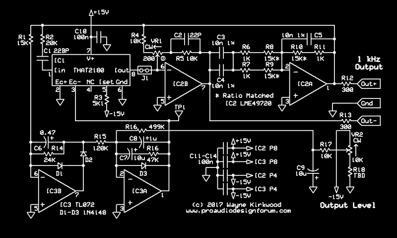
Subtractive VCA Stabilizes Ultra-Pure Sub-PPM Distortion Wien Bridge Oscillator
The only change from the previous version was to move VR1 to provide additional adjustment range to compensate for R4/R5 tolerance.
Using a notch filter I'm able to determine that the distortion is below -140 dBc.
I can only obtain that performance using the LME49720. No other dual op amp I've tried can come close. The op amps are clearly the most significant distortion contributor.
The subtractive VCA's highly non-linear control response is advantageous to stabilization and permits the "kick start" circuit in Vicktor's original, required for a FET, to be eliminated.
I haven't yet drawn Vicktor's floating TL431 shunt supply which I intend to use.
- Home
- Design & Build
- Equipment & Tools
- Low-distortion Audio-range Oscillator