They're just a rough first draft.
Vgs threshold, and transconductance curves are accurate, but other parameters may need changing.
Good enough to get a feel for how they might perform, but I might need to make some changes, so not ready to post publicly.
Yes please.
Do you think they are better than these very old models I found...
*SRC=2SJ79;QSJ79;MOSFETs P;Gen. Purpose;200V 500mA
.MODEL QSJ79 PMOS (LEVEL=1 VTO=-15 KP=122N GAMMA=18.6
+ PHI=.75 LAMBDA=1.04M RD=.84 RS=.84 IS=250F PB=.8 MJ=.46
+ CBD=862P CBS=1.03N CGSO=57.6N CGDO=48N CGBO=1.09U)
* -- Assumes default L=100U W=100U --
* 200 Volt .5 Amp 6 ohm Enh-Mode P-Channel MOSFET 07-28-1995
* 2SJ79, TOSHIBA, 1993 JAPANESE FET MANUAL, P.16
**********
*SRC=2SK216;QSK216;MOSFETs N;Gen. Purpose;200V 500mA
.MODEL QSK216 NMOS (LEVEL=1 VTO=15 KP=80M GAMMA=18.6
+ PHI=.75 LAMBDA=521U RD=.84 RS=.84 IS=250F PB=.8 MJ=.46
+ CBD=658P CBS=790P CGSO=26.4N CGDO=22N CGBO=852N)
* -- Assumes default L=100U W=100U --
* 200 Volt .5 Amp 6 ohm Enh-Mode N-Channel MOSFET 07-28-1995
* 2SK216, TOSHIBA, 1993 JAPANESE FET MANUAL, P.38
**********
I found in the internet this one....
.MODEL 2SJ79 PMOS (LEVEL=1 VTO=-.1 KP=40m GAMMA=18.6
+ PHI=.75 LAMBDA=1.04M RD=.84 RS=.84 IS=250F PB=.8 MJ=.46
+ CBD=862P CBS=1.03N CGSO=57.6N CGDO=48N CGBO=1.09U)
.MODEL 2SK216 NMOS (LEVEL=1 VTO=.1 KP=60M GAMMA=18.6
+ PHI=.75 LAMBDA=521U RD=.84 RS=.84 IS=250F PB=.8 MJ=.46
+ CBD=658P CBS=790P CGSO=26.4N CGDO=22N CGBO=852N)
but they behave fairly different from 2picodumbs models and I think he can judge best what is truth.....
ha, ha posting at nearly same moment.....
Yes and looking in similar places too
I agree that picoDumbs is no doubt in a better position to judge what is best here.
I found in the internet this one....
.MODEL 2SJ79 PMOS (LEVEL=1 VTO=-.1 KP=40m GAMMA=18.6
+ PHI=.75 LAMBDA=1.04M RD=.84 RS=.84 IS=250F PB=.8 MJ=.46
+ CBD=862P CBS=1.03N CGSO=57.6N CGDO=48N CGBO=1.09U)
.MODEL 2SK216 NMOS (LEVEL=1 VTO=.1 KP=60M GAMMA=18.6
+ PHI=.75 LAMBDA=521U RD=.84 RS=.84 IS=250F PB=.8 MJ=.46
+ CBD=658P CBS=790P CGSO=26.4N CGDO=22N CGBO=852N)
but they behave fairly different from 2picodumbs models and I think he can judge best what is truth.....
I will check them over.
No degeneration and BJT servo on OS only. Good temperature stability. Rail voltage stability not as good.
Attachments
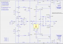
I managed to get the LT3092 current source to properly simulate in the circuit of post #1066, but the simulation runs very slowly, requiring about one hour for the temperature sweep.
ZM: There are two parallel servos here. I ran a 10 minute duration simulation at 25 watts and 20Hz and could not see any motor-boating. What do you say?
ZM: There are two parallel servos here. I ran a 10 minute duration simulation at 25 watts and 20Hz and could not see any motor-boating. What do you say?
Attachments
Instead of one hour simulation, you could make that ops and see for your self in real time ☺ Interesting work btw.
I have two competing designs to choose from. I suppose I could build both, requiring only a switch of the PCBs, since the power supply, heatsinks and enclosure would be the same.
I managed to get the LT3092 current source to properly simulate in the circuit of post #1066, but the simulation runs very slowly, requiring about one hour for the temperature sweep.
ZM: There are two parallel servos here. I ran a 10 minute duration simulation at 25 watts and 20Hz and could not see any motor-boating. What do you say?
looking good for me
(remember that I'm hardly expert .... both in LTSpice and general XA25 territory ...... pretty much shown with fact that my XA25 iteration is one millionth..... final!
 )
)now I'm on , say , 8mV span for DC offset between 25 and 70 , under 30mA Iq span , under 1mA span for drivers
will try in vivo in next few months , hopefully
I have two competing designs to choose from. I suppose I could build both, requiring only a switch of the PCBs, since the power supply, heatsinks and enclosure would be the same.
You don't need pcb for prototype of this ops, it's not that complicated, but I guess you are just lazy as I am... ☺
Seriously I don't think simulation for temperature compensation is reliable at all.
with 0R47 in rails , you can go much simpler route , with great stability (Iq tempco etc)
point of using all complications in biasing circ is to get down to , say , 0R1 or even lower
I'm not saying that 0R1 will result in better sounding or better behaving amp , just matter of exercise
point of using all complications in biasing circ is to get down to , say , 0R1 or even lower
I'm not saying that 0R1 will result in better sounding or better behaving amp , just matter of exercise

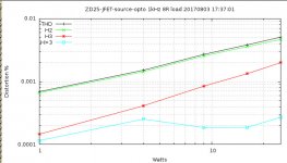
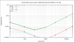
ZD25-JFET-opto
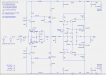
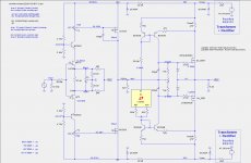
Here is a circuit with no degeneration that stabilizes both the front-end (FE) and output-stage (OS) bias and with appropriate resistor values appears to satisfy the XA25 specifications, except for the over-current shutdown. The schematic is shown without those values for now, but some performance plots are shown below.
Here is a circuit with no degeneration that stabilizes both the front-end (FE) and output-stage (OS) bias and with appropriate resistor values appears to satisfy the XA25 specifications, except for the over-current shutdown. The schematic is shown without those values for now, but some performance plots are shown below.
Attachments
-
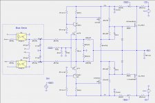 ZD25-JFET-source-opto-ps2-nodegen-simp-1c1b-FOR-FORUM.asc.jpg142.5 KB · Views: 408
 -
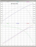
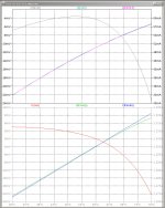
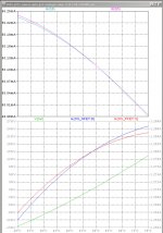 ZD25-JFET-source-opto-ps2-nodegen-simp-1c1b-FOR-FORUM.temp-sweep.jpg176.9 KB · Views: 305
 -
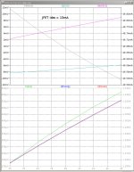
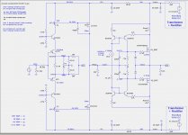
 ZD25-JFET-source-opto-ps2-nodegen-simp-1c1b-FOR-FORUM-1kHz-sweep.jpg74.1 KB · Views: 113
 -
 ZD25-JFET-source-opto-ps2-nodegen-simp-1c1b-FOR-FORUM-1Watt-fsweep.jpg91 KB · Views: 118
 -
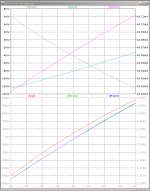
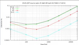 ZD25-JFET-source-opto-ps2-nodegen-simp-1c1b-FOR-FORUM-25Watt-fsweep.jpg91.3 KB · Views: 132

Here is a circuit with no degeneration that stabilizes both the front-end (FE) and output-stage (OS) bias and with appropriate resistor values appears to satisfy the XA25 specifications, except for the over-current shutdown. The schematic is shown without those values for now, but some performance plots are shown below.
Do you have a graph of frequency response and phase? Just wondering about stability given that you are applying all the feedback globally.
Unrelated point: I think there is degeneration here of the input JFETs due to the network between their sources. Doesn't Nelson tend to operate these at Idss these days? Even so, I can't see how all degeneration can be removed due to the need for the feedback resistor to ground.
Interesting bias circuit BTW. One issue I see is that this kind of approach will not lend itself well to doubling up (or more!) the output devices for extra power. Then again this may not be a goal for you.
- Home
- Amplifiers
- Pass Labs
- F4 Beast Builders