Another option is the Hammond 373HX (350-0-350) with 1650N (4.3K primary). Plate voltage would come in at 450V, and screen would need to be set at around 250V to optimize for this output transformer. It will demand less current from the power supply and should still deliver ~50 watts output.
There are distributors of Hammonds in Germany and Italy with fairly good prices (excl. VAT, incl. shipping) they are way cheaper than importing them or Edcors in low amounts from the states or Canada.
The european producers are more expensive as far as I have seen until now.
What I want to achieve is to run the 6L6GCs at max output, AB1 Plate 450V, Screen 400V, Grid1 -37V, Plate/Plate 5600Ohm, 55 W max output at 1.8%THD, AB2 shows 12watt less output wattage and more THD. Values for 2 tubes in pp.
This would require an OPT with approx. 2.8-3.3k ct.
Sounds about right. but I don't know of any off the shelf 3.3K outputs that will support 100 watts and that are available w/o large import fees. Edcor makes some but I expect import fees are exorbitant, nor do I know how well that particular model performs.
I've had pretty good results with the smaller Hammond iron. Their output transformers have healthy low end response. Must be a little careful in applying global feedback, but if you keep it under about 15 dB, it is not too hard to get a good sounding and stable amp.
I've had pretty good results with the smaller Hammond iron. Their output transformers have healthy low end response. Must be a little careful in applying global feedback, but if you keep it under about 15 dB, it is not too hard to get a good sounding and stable amp.
Last edited:
I was checking the european market for transformer producers, as proposed by parafeed813, and found a couple of small companies that are specialized in transformers for tube amps (beside the well known big ones).
One of them is EDIS, by Mr Ogonowski, ogonowski.eu. His company builds custimized power transformers, chokes, pp and se opts according to customer specs.
The contact and expertise is great, the prices are more than fair for a customized product.
The project can be continued.
One of them is EDIS, by Mr Ogonowski, ogonowski.eu. His company builds custimized power transformers, chokes, pp and se opts according to customer specs.
The contact and expertise is great, the prices are more than fair for a customized product.
The project can be continued.
If you don't mind only 4ohms out, this looks interresting.
Transfer Multisort Elektronik - On-line Catalogue | 200 000 products offered.
Mona
Transfer Multisort Elektronik - On-line Catalogue | 200 000 products offered.
Mona
The frequency range is too limited with max 12kHz, and 60Va is not enough with a quad of 6L6GCs rund at max output.
Offers from european and an american producer of opts with the following spec (pp, 150-200W, prim imp 2500-3000Ohm, 450mA max at 500V plate and 4&8Ohm output tab, 20Hz to 20kHz) are between 200 and 420 Euros, in comparison: the hammond 1650 with 200W and 1900Ohm prim imp is around 250Euros. The lower prices are eastern European products, and the higher ones central and northern European and US, all custom wound.
Thomas
Last edited:
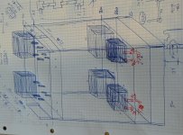
The schematic is finalized, with 2 rectifying options, one with silicone rectifiers and the second with parallel 5AR4 tubes (which I still tend to build since I never tried silicone rectification before).
The transformers and chokes are on the way from Poland (EDIS). Material is ordered.
I decided (was forced to change plans by my wife) that the project will not be built as two separate monoblocks but as a stereo amp (made of two mono sections, also powered and rectified seperately), since ther seems to be no more space in the living room for additional monoblocks....
So the rack and housing will be made of industrial aluminium profiles, and 4 and 8mm aluminium plates.
Can anyone tell me if a negative bias of -18V per 6L6GC tube with an additional 8.2R cathode resistor is ok if the plate voltage is around 500V and the screen voltage 450V? or do I blow the tubes this way?
I will keep you up dated
Thomas
Attachments
Last edited:
> is ok
No.
Can you read a data-sheet?
For start-up you "should" have Vg2/Mu(g2) of G1 bias to be sure the tubes can be started from very-low current. 450V/10= 45 Volts of G1-K bias.
At 500V, a 30W tube can only flow 0.060A before trouble. 0.060A in 8.2 Ohms is only 0.5V, negligible against a 45V need.
15V is not enough.
I suggest that you build the power supply on a separate chassis. This way you can have it tucked away somewhere and with all the AC components away from your tubes and signal circuits, your noise floor should be lower. And if you are using tube rectification, you can get different voltages by simply swapping rectifier tubes. The difference in B+ from a 5ar4 and 5r4 can be more than 60vdc. I mention this because if you ever want to get into single ended amps or another pp amp you can use the same power supply and thus save yourself a lot of effort and money by not having to make another power supply.
The plan is to build one stereo amp now with separate power supplies for each stereo section.
The height of the rack will be 1.15m sides will be 0.5m x 0.5m.
On the lower level there will be the power supplies, and on the top level the audio sections.
This might also give a possibility to just swap the audio section on top with the tubes and opts.
Thanks for your anser.
The height of the rack will be 1.15m sides will be 0.5m x 0.5m.
On the lower level there will be the power supplies, and on the top level the audio sections.
This might also give a possibility to just swap the audio section on top with the tubes and opts.
Thanks for your anser.
Attachments
Last edited:
Greetings from RojoLand!
Some thoughts and notes on this new project:
The Hammond 266N12 secondary is rated at 12.6 VAC 4 A (windings in series) or 6.3 VAC 8 A (in parallel). Your schematic shows an inexplicable "50.4 A"—! No matter; it is more than adequate to power two 5AR4 heaters. There is no center tap to be grounded as you suggest by the "center-tap" connection to ground. BUT — you would definitely NOT want this winding to be grounded! The 5AR4 is an indirectly-heated tube, but its heater is tied to the cathode at pin 8, so full B+ is present on that transformer. DON'T ground it! The correct way to diagram this transformer for the intended use is to show two paralleled windings; no center tap. The 0.33R resistor is nearly correct (exact value to drop 1.3 V at 3.8 A is 0.34210526315789 ohms, but who's counting? LOL), but a five-watt part is right on the edge (it will dissipate 4.94 W!). Use a 10-watt resistor here. Or, better yet, use the solid-state rectifier instead.
You show both fixed-bias and cathode bias here. While you can indeed do that, there's little point, plus you lose a little output power capability. Instead, change the 8.2R resistors to 1.0R and remove the bypass caps. This gives you test points for adjusting bias. A voltmeter will read cathode current directly in milliamps across a one-ohm resistor (i.e., 35 mA reads 0.035 V). The 6L6-GC datasheet (GE) shows design-maximum values of 500 V plate, 450 V screen (500 if operating ultra-linear as you are doing). Be aware of the 30 W maximum plate dissipation and 5 W max screen dissipation ratings.
Since this is to be a stereo unit, I would suggest using TWO 200R resistors and filter blocks, splitting the B1 supply into one for the left channel and another for the right. Ideally, the B+ to each channel's output stages would have some separation as well, since they are the largest power draws. Running both channels from a common supply invites cross-talk.
47K grid resistors into the 6L6s: Is there a reason? This is a rather stiff load for the phase splitter to drive. Remember that the 6L6s need only voltage, not current, and 100K grid resistors should be fine. No more than that, though.
Be aware that your custom-made output transformer may require some tweaking of the feedback compensation (both the 10K resistor and the 180 pF capacitor). Those values worked well for me with a 6V6-class amplifier and a stock Hammond universal transformer. 6L6s, and your OPT, are different. Leave 'em for now, but you may well have to play with those values.
I think it would be prudent to keep the B1 supply connected to the 6SN7 phase splitter but also to add a decoupling resistor and bypass capacitor for the 6SJ7 plate and screen supply (call that "B2"). Maybe use a 2.2K resistor and a 10 µF or so, 450 V capacitor. The extra filtering will help keep things quiet.
You call for only 10 nF coupling from the 6SJ7 plate to 6SN7 grid. This will work, but I suspect there'll be some bass rolloff. Try it, and if you do find some rolloff, I'd suggest doubling the cap to 22 nF. You don't need much more than that with the 1M grid resistor.
Back to the power supply: What is the purpose of the 100R/22 nF "zobel" network on the HT winding ahead of the transformer, and the second one following the bridge rectifier? Never seen that in a power supply before, but they're common on radio output circuits. Also, the heater winding is shown as center-tap-grounded (good) but there are also 120R resistors to ground on each "leg" of the winding. Why? Each resistor is drawing just over 26 mA and dissipating over 82 mW — doesn't sound like much but it's for no apparent purpose.
Bias supply: You have a 47K 1W in series with the 10K adjustment pot and 10K to ground. That's 67K across approximately -550 V (using your positive supply spec of 540-560 V). That's a bit over 8 mA draw. The 47K will drop approx. 385.82 V of that 550, leaving 164.18 V across that 10 µF **100 V** capacitor. You'll need at least a 200-volt-rated part there. The 47K will also be dissipating 385.82 (V) x 0.008 (I) = 3.08656 W, so that will have to be at least a five-watt part. Not sure I understand the purpose of the 1N4007 diode and 100K shunting resistor.
Hope these notes are of some help.
Take care,
—
J. E. Knox "The Victor Freak"
Hi rojoknox
Thank you for this very helpful and complete feedbach.
I will go for tube rectification, but will separate the 6sn6 ans the 6sj7 supplies.
Each mono section of tge stereo amp has its own supply, so the so the schematic in fact shows like one monoblock. So there should be no crosstalk.
I will change the cathode resistor of the 6L6GC to 1R, as recommended, neg. Bias voltage will be around -45V per two tubes, -90V in total.
Grid resistors will be changed to 100k.
The feedbackloop will be adaped when required.
I will try using a 10nF coupling cap, if I get bass rolloff, i will go to 22nF.
The zobel network and the shunt will be removed, I read that these might help to keep hum low or gone.
The 120R resistors on the heater supplies shall keep heater induced hum away. I did this with my 6V6 monoblocks too, even if it might not be really helpfull. There should be enough heater current available to do so.
For the negative supply, i will see what resistor I need in place of the 47k to come closer to 100V instead of 170.
Thanks a lot once again.
I will keep you updated on the project
Greetings from RojoLand!
"Bias voltage will be around -45 V per two tubes…" That's OKeh. "…-90 V in total." That is NOT! The -45 V bias appears on all the tubes; it is not additive. If you were to bias the tubes to -90 V they would be totally cut off and do nothing.
You have planned a bias adjustment (good) but it is common to all tubes (not as good). It *will* work, but you must then have well-matched output tubes, lest one or two draw more current than the others. Since you are going "all-out" on this amplifier, consider making the bias adjustable for each tube pair. That will entail using two pots across the bias supply, with each pot's wiper going to one pair of 6L6-GC control grids through a grid resistor (as noted before, 100K — no more than that). A capacitor from the "bottom" of the grid resistor to ground is a good thing too (4.7 or 10 µF will do, 100 V — note polarity!). A 25K or 50K pot would be fine. Add a 220K or 330K resistor from the "high" side of the pot to the wiper, to provide protection should the pot wiper happen to break contact. With this scheme, the two bias resistors in the current schematic would NOT be joined. You could go a step farther and make EACH 6L6 have separate bias, but that will also require duplicating the coupling capacitors and separating the links between the tube grids — probably more complication than you want to get into.
"The 120R resistors on the heater supplies shall keep heater induced hum away." The grounded center tap goes most of the way toward preventing that. Indeed, a better way is to dispense with those 120R resistors AND the grounded center tap, and instead connect the center tap to a source of about +40 to 50 VDC; a voltage divider across a well-filtered B+ rail [such as "B2" described earlier] will do the job. If the B+ rail is, say, 330 V, a 270K and 47K in series across the rail will total 317K, draw a hair over one milliampere (1.04100946372 mA to be more precise!) and provide a heater lift voltage of about 48.93 V at the resistor junction. A 0.1 µF film cap (100 V or larger) from the resistor junction to ground bypasses any noise.
"I will see what resistor I need in place of the 47k…" Remember, Ohm's Law is your friend.
Take care,
—
J. E. Knox "The Victor Freak"
Hi Rojoknox
I have adapted the schematic, but: concerning biasing of the quad; is it also possible to not bias the paralleled 6L6GCs but to bias each pair (first pair and second pair) by using an additonal signal supply for these via a second decoupling cap on each LTP output? I added this porposal to my schematic, since I found this on an amp schematic with 3 paralleled pairs of EL34 (as far as I can remember).
I have added a second bias adjustment, with a 25k pot, a 220k resistor on the high.
The grids resitsors (on the grid side) are now grounded via a 4.7uF/100V cap, just to make sure; the negative side of the cap is to the grid/the positive to ground, isn't it, since there is negative voltage (the same for all the negative bias caps)?
I will increase the base of the heater voltage in case of hum issues, as you proposed.
Best regards, Thomas
Attachments
Greetings from RojoLand!
As noted in the private message, you can indeed bias each pair separately, but that's less desirable because it doesn't address possible imbalance between the pair. Full individual bias adjustment is best, if more complicated. If you're cool with the twinned coupling capacitors, you've already done most of the work. Add two more bias controls, separate the grid resistors and you're there! (Oh, and definitely remove the 220 µF cathode-bypass caps as they are no longer needed. You are now showing "1 or 8.2R" for the cathode resistors; stay only with 1.00 ohm parts here as the cathode current can be read directly across them. You *can* use 10.00-ohm parts but the voltage reading across them will be 10 times the current in milliamperes. If you were to use 8.2R parts, you'd have to do some math to get any meaningful reading") )
)
You have changed the bias-source dropper resistor to 100K, but also lowered the wattage to only one watt! Why is that? The 100K resistor now is in series with the parallelled pair of 25K pots, for a total of 112.5K across -550 V, and current of approx. 4.8889 mA. The voltage at the top of each pot is now approx. -61.111 V, which is fine and dandy. But the 100K resistor is dissipating a hair over 2.39 W. Better use a five-watt resistor here! Each adjuster pot will dissipate just shy of 300 mW, so they should be one-watt or, better, two-watt parts. Half-watt pots might get a bit warm and fail sooner. The 220K resistors across the top and wiper of each bias pot need not be one-watt parts. Worst-case, the 61.111 V would be across them (and you'd NEVER run the amp this way!), and dissipation would be just under 17 milliwatts. In that condition, the 220K is effectively paralleled with the 25K adjuster pot which totals approx. 22.449K. This slightly increases the drop across the 100K resistor. But since you wouldn't be running the amp like that (no bias on the tube!!), it's not a real concern.
I don't understand the purpose of these "grounding caps." Doing this would give you an extremely muffled amplifier (if indeed any sound at all came out), as you would be shorting out most all of the signal! Remove those capacitors. You are correct in that if those caps WERE needed, the negative end would have gone to the grid and the positive end grounded. But there is no explicable purpose for them at that point. The 22 µF capacitors on the wipers of the bias pots connect the same way, positive-ground. You can use 100-volt or even 63-volt parts there; 250 V parts are overkill. If you have 'em, fine, but there should be no more than around -45 V at that point.
It is customary when drawing electrolytic capacitors on a diagram to show the cap's positive lead with a small '+' and the negative lead with a curved line. Film, mica and ceramic capacitors are shown with two parallel lines and no polarity mark.
Also just noticed the 220K and 180K resistors in series from "B2" source to the 6SJ7 screen (pin 6). This can be a single 390K 1/2-watt resistor. Even if the screen were shorted to ground (not likely!), 300 V across 390K is less than a milliamp (indeed, just under 770 *microamps*) and the resistor would dissipate about 230.77 mW. No need for one-watt resistors, much less two separate parts!
You also will not need five-watt parts for the one-ohm 6L6 cathode resistors. It would take one volt across the one-ohm resistor to dissipate one watt, much less five, and with one volt across the resistor, the tube would be passing an impossible 1000 mA. It would glow red and burn out trying! (The datasheet maximum cathode current — plate plus screen current, at maximum signal, with 450 V plate and 400 V screen voltages — is 232 mA for two 6L6-GC tubes in Class AB1 push-pull, or 116 mA per tube.)
Take care,
—
J. E. Knox "The Victor Freak"
As noted in the private message, you can indeed bias each pair separately, but that's less desirable because it doesn't address possible imbalance between the pair. Full individual bias adjustment is best, if more complicated. If you're cool with the twinned coupling capacitors, you've already done most of the work. Add two more bias controls, separate the grid resistors and you're there! (Oh, and definitely remove the 220 µF cathode-bypass caps as they are no longer needed. You are now showing "1 or 8.2R" for the cathode resistors; stay only with 1.00 ohm parts here as the cathode current can be read directly across them. You *can* use 10.00-ohm parts but the voltage reading across them will be 10 times the current in milliamperes. If you were to use 8.2R parts, you'd have to do some math to get any meaningful reading
)You have changed the bias-source dropper resistor to 100K, but also lowered the wattage to only one watt! Why is that? The 100K resistor now is in series with the parallelled pair of 25K pots, for a total of 112.5K across -550 V, and current of approx. 4.8889 mA. The voltage at the top of each pot is now approx. -61.111 V, which is fine and dandy. But the 100K resistor is dissipating a hair over 2.39 W. Better use a five-watt resistor here! Each adjuster pot will dissipate just shy of 300 mW, so they should be one-watt or, better, two-watt parts. Half-watt pots might get a bit warm and fail sooner. The 220K resistors across the top and wiper of each bias pot need not be one-watt parts. Worst-case, the 61.111 V would be across them (and you'd NEVER run the amp this way!), and dissipation would be just under 17 milliwatts. In that condition, the 220K is effectively paralleled with the 25K adjuster pot which totals approx. 22.449K. This slightly increases the drop across the 100K resistor. But since you wouldn't be running the amp like that (no bias on the tube!!), it's not a real concern.
The grids resitsors (on the grid side) are now grounded via a 4.7uF/100V cap, just to make sure; the negative side of the cap is to the grid/the positive to ground, isn't it, since there is negative voltage (the same for all the negative bias caps)?
I don't understand the purpose of these "grounding caps." Doing this would give you an extremely muffled amplifier (if indeed any sound at all came out), as you would be shorting out most all of the signal! Remove those capacitors. You are correct in that if those caps WERE needed, the negative end would have gone to the grid and the positive end grounded. But there is no explicable purpose for them at that point. The 22 µF capacitors on the wipers of the bias pots connect the same way, positive-ground. You can use 100-volt or even 63-volt parts there; 250 V parts are overkill. If you have 'em, fine, but there should be no more than around -45 V at that point.
It is customary when drawing electrolytic capacitors on a diagram to show the cap's positive lead with a small '+' and the negative lead with a curved line. Film, mica and ceramic capacitors are shown with two parallel lines and no polarity mark.
Also just noticed the 220K and 180K resistors in series from "B2" source to the 6SJ7 screen (pin 6). This can be a single 390K 1/2-watt resistor. Even if the screen were shorted to ground (not likely!), 300 V across 390K is less than a milliamp (indeed, just under 770 *microamps*) and the resistor would dissipate about 230.77 mW. No need for one-watt resistors, much less two separate parts!
You also will not need five-watt parts for the one-ohm 6L6 cathode resistors. It would take one volt across the one-ohm resistor to dissipate one watt, much less five, and with one volt across the resistor, the tube would be passing an impossible 1000 mA. It would glow red and burn out trying! (The datasheet maximum cathode current — plate plus screen current, at maximum signal, with 450 V plate and 400 V screen voltages — is 232 mA for two 6L6-GC tubes in Class AB1 push-pull, or 116 mA per tube.)
Take care,
—
J. E. Knox "The Victor Freak"
Started building
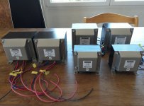
Just started building my amp.
The two power supplies have been built, using 2 parallel 5AR4 tubes, separate filament transformer.
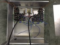
On the top of the lower compartment there are the power trannies and a 10H choke, inside are the caps.
The two tubes going up into the upper (amp)compartment contain the DC and ground wires and the other the AC filament wires.
Each section has its own power supply.
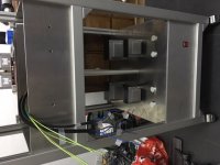
Voltage regulator (for the output tube screens) and bias regulators will be placed in the upper compartment.
The upper compartment will be built to make it possible to exchange the tube sections to make it possible to use other tube types later, all DC and AC connections will be made with connectors.
Just started building my amp.
The two power supplies have been built, using 2 parallel 5AR4 tubes, separate filament transformer.
On the top of the lower compartment there are the power trannies and a 10H choke, inside are the caps.
The two tubes going up into the upper (amp)compartment contain the DC and ground wires and the other the AC filament wires.
Each section has its own power supply.
Voltage regulator (for the output tube screens) and bias regulators will be placed in the upper compartment.
The upper compartment will be built to make it possible to exchange the tube sections to make it possible to use other tube types later, all DC and AC connections will be made with connectors.
Attachments
Last edited:
Thomas,
I came onto this thread late, so am not going to suggest further changes; all good advice so far. I thought though that perhaps what I have done with quad 6L6GCs may serve as encouragement.
556V on anodes, 456V on screens (regulated). UL tap: 26% (separate screen windings). Fixed bias adjustable 40V - 50V (neg.) OPT primary impedance: 2,9K a-a. OPT efficiency 90% (own wind on C-core). 6L6 cathode current 50 mA each. Output 110W sine wave into 8 ohms resistive (when the mains voltage is on par!).
(My power supply is somewhat different, using a choke input filter for improved regulation. Main filter capacitance is 490µF 900V from 6 x 330µF 450V single ones 'stacked'.)
Wishing you success!
(Just beware of the h.t. around. I once touched the main supply. I can assure you it is NOT pleasant; possibly lucky to be able to still write here ....)
- Status
- This old topic is closed. If you want to reopen this topic, contact a moderator using the "Report Post" button.
- Home
- Amplifiers
- Tubes / Valves
- 6L6 quad push pull monoblock project