Or concentrate on the "analog" bar at the bottom of the LCD screen if your meter has oneOne other thought about bias setting. It would be easier with an analog meter. With modern digital meters it is very easy to get fixated on the wrong digits. The goal is 3.6V, but anything in the range of 3.5-3.7 is fine, and probably more like 3.3-3.9. if it is drifting but staying in the right range you have no worries. Obsessing about changes from 3.548 to 3.612 is not helpful. If you had an old analog meter and saw the needle gently moving around 3.6 +/- 0.1 you wouldn't care about the second digit after the decimal!")

Or try an IXYS IXTP 01N100D instead of R13. Test that Mosfet with 20V on a breadboard with 330 Ohm gate resistor and a 100R rheostat on source pin for 18mA. Rail on drain pin, output return between the gate and source resistors. Replace the rheostat value with a fixed resistor. Solder the resistors directly on the pins with very short legs and put the whole thing in R13's place as a 2 pin CCS device. Now the 2x K369s current will be fixed by stronger force. PSRR for harmonic noise is going to improve, but little extra device hiss is also possible. You decide what you like better in the end i.e. passive resistive CCS or active DMOS CCS for those JFETs.
You mentioned that idea once before, and it is intriguing. I like the idea of an active CCS for the front end, and I suspect even in a high gain configuration the noise penalty would be very small (though I would like to see the 1/f noise), but I also don't want to rework my phono preamp which is working so well and sounds so good!
As for the VTVM reference I was just remembering doing tape deck tune-ups many years ago. We had a digital meter on the bench (all red LEDs back then) but doing finicky adjustments was much easier with the analog meter with a fairly slow ballistic movement. Today we digital meter readers tend to focus on the least significant digits, because we can, ignoring the fact that they are not significant.
As for the VTVM reference I was just remembering doing tape deck tune-ups many years ago. We had a digital meter on the bench (all red LEDs back then) but doing finicky adjustments was much easier with the analog meter with a fairly slow ballistic movement. Today we digital meter readers tend to focus on the least significant digits, because we can, ignoring the fact that they are not significant.

Well, my SALAS is playing music.
Lots of work to do since I am having to learn a new tonearm's quirks. Luckily we think this is fun!
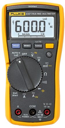
Did not have an analog meter but had a FLUKE meter used by air conditioning contractors (since that is who owned this one) and it has a slower response time than my newer and "tricker" one which made finding a resting spot much easier.
Now to start finding the best load for the MC. Taking Salas's advice and starting with lower loads. Initially into the base 47K which sounds OK when all is soft but gets strident as the level rises. Think I will begin with 1K.
Thanks again to nezblue and Salas for excellent advice. An additional appreciate to Salas for being Salas.
Lots of work to do since I am having to learn a new tonearm's quirks. Luckily we think this is fun!
Did not have an analog meter but had a FLUKE meter used by air conditioning contractors (since that is who owned this one) and it has a slower response time than my newer and "tricker" one which made finding a resting spot much easier.
Now to start finding the best load for the MC. Taking Salas's advice and starting with lower loads. Initially into the base 47K which sounds OK when all is soft but gets strident as the level rises. Think I will begin with 1K.
Thanks again to nezblue and Salas for excellent advice. An additional appreciate to Salas for being Salas.
Rick thanks for your kind words, nice to know you are proceeding well with the settings.
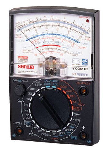
My first meter was analog of course, a Lafayette TE-12. Japanese vintage model of shiny black bakelite case like a 1950s telephone with an arched top beautiful panel. Served me for many years and it survived a number of drops until I managed to break it.
I ordered a modern Pro'sKit MT-2017 budget analog meter, unfortunately of rather gaudy colors, to also have an analog once again. For bringing back those watch the needle memories. Plus there are special cases of measurement where some analog practicality still excels as Nezbleu correctly reminded.
Well now that I am hearing SALAS sound from my phono and being one to NEVER leave well enough alone I have tried something new with my power supply.
This is an absurdly overbuilt supply. I had four of the HAMMOND 5 Hy (26R) chokes and four of these giant DUCATI PP caps (somehow used for solar installations) 1500 uF in an LCLC configuration.
Then I read a new post on Jeff Day's blog which has an article by Mr. Yazaki of SPEC CORP about modifying the MARANTZ 7 preamplifier. I am an unabashed fan of Mr. Yazaki. He, along with Mr. Salas and a few others occupy my audio pantheon.
I have long been fascinated by the use of a half wave rectifier in this preamplifier. Obviously this was not done as a cost saving measure but no one has said much about it other than to state it as a matter of fact. In this article Mr. Yazaki replaced the aging selenium rectifier with his favorite diode the STT6112TV2. I had intended to use these in a bridge but they are expensive and I figured a diode recommended to me by Mark Johnson (QUASIMODO snubber tool) and figured with the secondary snubbed the STT was overkill (as if I feared overkill, but I am cheap).
SO after reading this article I thought I should quit thinking about it and try it with my SALAS. I removed the bridge. Luckily I had one of these diode pairs on hand. They come in the hockey puck package/two diodes. Using only one. I had to put a cap after the rectifier, in this case 14 uF where before it was a choke input filter.
Had to play around with that value and the bleeder to get the right input voltage. Now that I am back at it this took very little time. Plus the DUNCAN AMPS PS tool is very helpful once you establish a baseline.
Of course, everyone is expecting me to say it sounds much better and you will not be disappointed. Now whether I am simply hearing the sound of this rectifier (which I use in my power amplifiers) versus any real comparison of half wave versus bridge will have to wait for me to compare STT half wave versus bridge.
What I hear is a great reduction in noise - not the noise of typical analog noisiness - this is more like when you hear a digital setup that is very low in digital noise. The kind of noise that sounds intertwined with the signal. Most analog noise is separated from the music signal. I know this is getting fanciful. This is a noise I did not recognize as a noise until it was gone.
So thinking of Michael Green's thoughts on acoustic control devices in the listening room - he opined it was better to damp one large resonance instead of lots of smaller ones. Could this be what is happening? The rectifier itself is making a soft burr noise that is also heard faintly in the speaker when one's ear is in the horn. So there is THAT noise which is not heard in my listening chair but there is another form of noise that has been reduced that allows something much more musical to be heard.
Like a dark cloud has been removed from the proceedings - a dark cloud, like a fog that is everywhere within the instruments and the ambience.
When I was playing with an AIKIDO phono stage it is similar to the difference heard between a 5AR4 and a 274B. The former was dark and the latter was if the lights had been turned on - not bright - but an aural equivalent of greater visibility.
So if anyone might give this a try I would appreciate being told I am nuts or thank you. Sid Smith must have been on to something.
Hello Rick,
I read your last posts and I feel that I might have a useful opinion saving you some space inside the case and of course bring also ease of mind if considered valid.
So here it goes:
Regarding STT6112TV2 used as a rectifier for a project with low voltage and power requirements as the simplistic jfet riaa or of any other pre-amp using jfets or even bjt's is a drawback and overkill instead an improvement over lets say the lowest voltage rated MUR's available like 405-420 which have half the recovery time; and also half of Vf and a much lower If. Having all those into consideration, in any rectification configuration ; a rectification using MUR's or rectifiers of the same scope, as close as possible to the used Voltage or Current requirements will outperform in any aspect a corresponding rectification with any ammount of oversizing (keeping in mind that reaction times and dropouts increase with current/voltage capabilities) and i am talking about diodes only.
Filtering capacitors and networks used to lower ripple for the absolute maximum power consumption of the given circuit are fairly easy to calculate and measure ... but that's way a different subject, here oversizing can't do any harm ... but from a point(also fairly easy to measure)... can't do good either; and here i slip off your topic.
Regarding the points of the quality of the resulting sound I can not debate since there is not much information to collaborate the "The kind of noise that sounds intertwined with the signal" instead, a lower ripple will give a lowered analogue noise to any given circuit ripple which can be handled using cans of capacitors ; and ofcourse tons of copper worth of coil ... inductors.
Making things short I can not see a viable scenario/argument on why using a grosely oversized diode rectification scheme would do anything good to the resulting DC (not to mention the resulting sound) ... most it can do is the same with lower obtained voltage. So rule of thumb for me is keep the diode as close as possible to the needed voltage but no lower than double and 4 ~times the current (for lower dissipation). And buffered with no lower than 10 times the needed capacitance for the highest power usage admissible ripple, and where possible throw in some H of good old ferrite core coils for very low currents and air cored for high loads(amps)... of course those are chosen both empirically and measured over time and might vary with information or valid arguments
... thats it,
Regards,
Calin.
I read your last posts and I feel that I might have a useful opinion saving you some space inside the case and of course bring also ease of mind if considered valid.
So here it goes:
Regarding STT6112TV2 used as a rectifier for a project with low voltage and power requirements as the simplistic jfet riaa or of any other pre-amp using jfets or even bjt's is a drawback and overkill instead an improvement over lets say the lowest voltage rated MUR's available like 405-420 which have half the recovery time; and also half of Vf and a much lower If. Having all those into consideration, in any rectification configuration ; a rectification using MUR's or rectifiers of the same scope, as close as possible to the used Voltage or Current requirements will outperform in any aspect a corresponding rectification with any ammount of oversizing (keeping in mind that reaction times and dropouts increase with current/voltage capabilities) and i am talking about diodes only.
Filtering capacitors and networks used to lower ripple for the absolute maximum power consumption of the given circuit are fairly easy to calculate and measure ... but that's way a different subject, here oversizing can't do any harm ... but from a point(also fairly easy to measure)... can't do good either; and here i slip off your topic
.Regarding the points of the quality of the resulting sound I can not debate since there is not much information to collaborate the "The kind of noise that sounds intertwined with the signal" instead, a lower ripple will give a lowered analogue noise to any given circuit ripple which can be handled using cans of capacitors ; and ofcourse tons of copper worth of coil
... inductors.Making things short I can not see a viable scenario/argument on why using a grosely oversized diode rectification scheme would do anything good to the resulting DC (not to mention the resulting sound) ... most it can do is the same with lower obtained voltage. So rule of thumb for me is keep the diode as close as possible to the needed voltage but no lower than double and 4 ~times the current (for lower dissipation). And buffered with no lower than 10 times the needed capacitance for the highest power usage admissible ripple, and where possible throw in some H of good old ferrite core coils for very low currents and air cored for high loads(amps)... of course those are chosen both empirically and measured over time and might vary with information or valid arguments
... thats it,
Regards,
Calin.
AS I said, I did not use this rectifier as a bridge because I worried it might not work so well but with this duty I figure it is justifiable. This rectifier made a beneficial difference in the sound of my First Watt amplifiers so I do have previous experience with it. The difference in the presentation before and after is similar to what I experienced with the amplifiers.
Most of the stuff in the power supply is stuff I have had laying about for years, might as well use it for something. I will eventually attempt to make the supply smaller but with capacitors the size of riding lawn mower batteries it won't be possible to do much.
The main point was regarding noise, especially the difference with obvious noise and the noise, like digital noise, that is intertwined in the signal - not easily ignored by the ear brain like clicks, pops, groove noise, hum, etc.
Figure it is like it is with all devices on Earth - you have the "envelope" - you can stretch it this way or that way but not both ways at once. Compromise is inevitable. So the question I am posing is: what if our obsession with removing the obvious noises like being able to put one's ear to the loudspeaker and not hear any noise puts us at the risk (?) of introducing more pernicious noise that is not easy for the ear/brain to ignore?
I am thinking as I continue to listen to this setup that is what is happening. I do hear much more noise with my ear to the horn at high level settings (which I cannot hear at my listening chair) while I am thinking I am perceiving less junk in the space between the notes and within the notes.
Time will tell if that is the case. At this point I am hearing a much more attractive tonal balance and a clarity that was not there before.
Mr. Yazaki replaced the aging selenium rectifier with his favorite diode the STT6112TV2.
Rick, thanks for your report. I am also a half wave fan and would like to remind that transformer power rating required for this mode is more than double the normal.
Btw, the correct type is STTH6112TV2.
Did not quite catch the rectifier type you ended up using. Was it supposed to be kept a secret?
No, not a secret, it is the aforementioned STTH6112TV2 and STTH6112TV1.
As I mentioned the TV2 is no longer available and only the TV1 version is available from MOUSER and DIGIKEY. They are the same except for how the diodes are arranged. Used to be two versions and now there is only one.
I have one channel using a STTH6112TV2 I had on hand and the other channel is using the STTH6112TV1 I had to get. That is when I found out they had dropped one. I do not hear any difference between the two.
Since you are as crazy as I am have you found it typical for the half wave diode to produce more noise than a bridge?
Since I am still working with this supply it is out in the open and if one is real close to it you can hear the diodes buzzing.
My transformers are absurdly over-specified at 200 VA each.
I continue to be pleased with the sound of this arrangement. Mr. Smith was on to something!
That's correct. When to do MM configuration, R2 becomes large.
"For circa 5mV MM cartridge don't populate Q2,R3, use 91R R2, 5.6K 1W R13, 1.8K R4, for 40dB gain and proper overload margin. Use 100nF C3 only value when with MM.
Choose Q1 between channels from a 10.5-12.5mA range at 5% IDSS pair tolerance."
"For circa 5mV MM cartridge don't populate Q2,R3, use 91R R2, 5.6K 1W R13, 1.8K R4, for 40dB gain and proper overload margin. Use 100nF C3 only value when with MM.
Choose Q1 between channels from a 10.5-12.5mA range at 5% IDSS pair tolerance."
No... I've got a friend over (I told him if he bought some chassis and built it, he could have it) and we're in a rush building it because his plane is in the morning. I'll get a few photos and write up any good pointers I can remember, there's not a bunch of mystery to the layout.
BTW, this thing sounds FANTASTIC!
BTW, this thing sounds FANTASTIC!
Last edited:
I also have a question for the leds Vf .
I have more than 50 leds of different colors and shapes, and i did not manage to get a combination of a quartet with 7.75V total voltage drop (is manageable only in a series of 5) and as well a 5.8V (is manageable only in a series of 4)
I am measuring as suggested using a 9V battery in series with a 1.5k and a multi-meter with one led at a time; then i subtract the value obtained on the screen from the battery's voltage.
Is it normal?
A 1k0 resistor will give a reading on the DMM (set to 20.00Vdc) that is in milli-amps, no metal arithmetic required.
The Vf + Vresistor add up to the battery voltage.
Thus a reading of Vres=6.80Vdc means the current is 6.8mA (LED very bright) and a reading of Vf should be 2.2Vf (probably a green, or yellow)
If you want to check at various currents, then adding a 5k pot wired as a variable resistor allows the total resistance to be varied from 1k0 to 6k0. You still monitor current by measuring the Vdrop on the 1k0 resistor. The 5k pot allows currents from ~1mA to ~7mA to be set and Vf to be measured.
An alternative is to use a CCS with the current set to your chosen value.
Then just plug in each LED and read off the Vf. This is much quicker and can use a little jig wired around an 8pin DIL socket connected to your battery, or a Lab Supply.
Last edited:
- Home
- Source & Line
- Analogue Source
- Simplistic NJFET RIAA