Hi, I'm putting together a TDA2822m amp but I've noticed in the datasheet schematic that the Boucherot cell is placed after the output coupling capacitor as opposed to right at the output pin like many other IC's recommend.
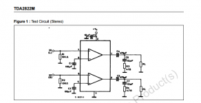
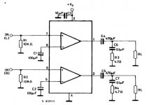
For example this is from the datasheet of the TDA2822m

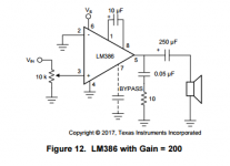
Where as this is from the LM386 datasheet

As you can see the output RC zobel networks are in different places, is the placement on the TDA2822m datasheet a mistake or does it not matter where I place it? I've taken apart a commercial clock radio with a TDA2822m and the zobel network was placed right at the output of the IC before the coupling capacitor.
tl;dr is it better to place the zobel network before or after the output coupling capacitor?
Thanks!
For example this is from the datasheet of the TDA2822m

Where as this is from the LM386 datasheet

As you can see the output RC zobel networks are in different places, is the placement on the TDA2822m datasheet a mistake or does it not matter where I place it? I've taken apart a commercial clock radio with a TDA2822m and the zobel network was placed right at the output of the IC before the coupling capacitor.
tl;dr is it better to place the zobel network before or after the output coupling capacitor?
Thanks!
Last edited:
is it better to place the zobel network before or after the output coupling capacitor?
It's to ensure stability, so place it as close to the amplifier output as possible.
Make sure the Zobel capacitor voltage rating is more than the power supply voltage.
If you plan to run/test at high power/frequency, use a Zobel resistor of several Watts rating.
It's to ensure stability, so place it as close to the amplifier output as possible.
Make sure the Zobel capacitor voltage rating is more than the power supply voltage.
If you plan to run/test at high power/frequency, use a Zobel resistor of several Watts rating.
Thanks, so is it better to place it before or after the output speaker coupling capacitor?
Is it best nearest the amplifier because of the output coupling capacitor? I understand that if a coil is fitted that should be close to the amplifier but thought, with a DC coupled amplifier the capacitor/resistor network is ideally at the speaker end and only at the amplifier end for practical mass produced amplifier stability?
the output coil is there to help isolate cable capacitance from the output stage. Capacitance loading of the output changes the stability margins and can make an amplifier ring or worse oscillate.
But zero loading by disconnecting the loudspeaker cables leaves the amplifier without any defined load and some can become less stable in this condition. Adding an Output Zobel gives the amplifier a defined HF load to help control the amplifier behaviour.
BUT !
the amplifier Output Zobel can only pass high frequencies. Much higher than the audio band and into the RF region. This requirement to pass HF & RF demands an ultra low trace/cable impedance and that equates to fitting the smallest components with the shortest leads/traces around the output device/s
Thanks everyone, it looks like I'll connect it directly to the output pins then. Could STMicroelectronics putting it after the output coupling capacitor in the TDA2822M datasheet be an error?
It turns out that this configuration might be called a Boucherot cell as I'm only using the resistor and capacitor as shown in the datasheet and no extra inductor. Its not going to be a hifi system by any means, just a little board a few square inches in size with PCB terminals to connect different speakers.
Both the output coupling capacitors and Boucherot cells will be on board so they will never be more than a few cm away from the IC anyway.
the output coil is there to help isolate cable capacitance from the output stage. Capacitance loading of the output changes the stability margins and can make an amplifier ring or worse oscillate.
They do esp. on higher power designs, they call them "optional" parts. Engineers want /like to use them for bullet proof designs. The chip sellers marketing groups want to show lowest parts counts for customers (bean counters) so they delete them. If you know what speakers and cables are being used you can delete them, usually/ , so in the end it is up to customer to design and verify with testing. In small power amps the bad loading with HF decoupling inductors deleted can be tolerated with out destroying parts.
So even with a 1W chip amp like mine they can be beneficial? How would I go about making one? I've got plenty of magnet wire and resistors laying around.
Edit: Saw your edit above. Still, what is the name given to these output inductors? I'd like to read up on them and find out more about them as this is the first time I've really given them a thought.
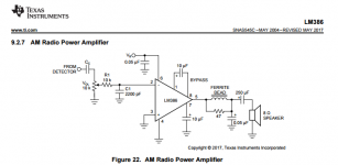
Is this the same sort of thing as seen in the LM386 datasheet?

Last edited:
So even with a 1W chip amp like mine they can be beneficial? How would I go about making one? I've got plenty of magnet wire and resistors laying around.
Edit: Saw your edit above. Still, what is the name given to these output inductors? I'd like to read up on them and find out more about them as this is the first time I've really given them a thought.
Is this the same sort of thing as seen in the LM386 datasheet?
View attachment 619752
Sorry my original post which you quoted above was mistakenly deleted. (multiple browsers opened don't help)
I don't give them a name. I call them output inductors. Or 'output decoupling inductors' minimizing the effects capacitance loads above the upper audio frequency range.
In most cases they are simple solenoid air coils ~ 0.5 - 2 uH. Also large ferrite beads with one or two turns is fine for ~1 Watts.
IMO Normally the risk is very low for excluding them from your 1W chip audio designs. Although some fringe applications may still need them E.g. PCBs with ground planes.
Last edited:
Sorry my original post which you quoted above was mistakenly deleted. (multiple browsers opened don't help)
I don't give them a name. I call them output inductors. Or 'output decoupling inductors' minimizing the effects capacitance loads above the upper audio frequency range.
In most cases they are simple solenoid air coils 1-2 uH. Also large ferrite beads with one or two turns is fine for ~1 Watts.
Do they go in series with the + speaker lead at the output terminals and do I need to put a resistor in parallel with it?
Do they go in series with the + speaker lead at the output terminals and do I need to put a resistor in parallel with it?
yes , a parallel resistor to damp inductor resonance. Most folks wind a coil over the diameter of a power resistor and connect them to the resistors leads.
Last edited:
yes , a parallel resistor to damp inductor resonance. Most folks wind a coil over the diameter of a power resistor and connect them to the resistors leads.
Gotcha, what size resistor would be good for TDA2822m @9-12v feeding an 8 ohm load?
If I was building a few amps I would leave these parts off.Gotcha, what size resistor would be good for TDA2822m @9-12v feeding an 8 ohm load?
a 4 to 10 ohm 1/4 W resistor for 1W app is plenty.
- Home
- Amplifiers
- Chip Amps
- Zobel network placement
