An AD797 thread had this post, some years back.
Anyone have any ideas on the best way to do this?
Best of all if Scott could show his own idea")
David
I have never seen a follow-up but the idea still has appeal....I still would like to make a fully compl[e]mentary version.
Anyone have any ideas on the best way to do this?
Best of all if Scott could show his own idea
David
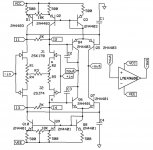
I've never been a big fan of fully comp since you have to match N to P type and they
never really match due to device physics. I also do not like a single ended VAS with
a current source on the other side which leads me to topologies where the other diff
pair output is used to drive the other side of a push-pull VAS. There are many examples
such as the APT power amp, several from Harman Kardon, and this Onkyo just as an
example - the front end to the VAS, nothing more:
http://www.diyaudio.com/forums/soli...r-complementary-output-stage.html#post5050126
What do you see as the reasons to go full comp?
Another advantage of a single ended diff pair is that many FETs are more available in
N type only.
Curious to see what Scott has to say.
...What do you see as the reasons...
One of the benefits should be even lower noise.
Additional input transistors in parallel is a classic way to lower Vnoise.
A complementary IPS pair is effectively a way to do this but has the benefit that input bias currents are cancelled rather than added.
Whereas the AD797 has an input bias cancellation circuit that inevitably adds some noise, as Scott himself has pointed out. The datasheet published by AD is very quiet on the subject, which is appropriate I suppose.
It should be easier to achieve cancellation of current induced distortion and hopefully some parasitics may cancel.
And, while I understand that the physics prevents accurately complementary devices, symmetry does look nice.
Curious to see what Scott has to say.
Me too, it seems people are a bit hesitant to post before they read his comments.
Best wishes
David
Last edited:
JFETs solve the input bias issue, yes?
Yes, but the lowest noise inputs are still BJT, I believe the new edition of "The Art of Electronics" has the best information on this, I need to buy a copy.
And a complementary self-biased JFET CFA is also a nice solution.
The complementary input JFET saves a VAS current source or an APT style current mirror so it's actually simpler, with lower noise as a bonus if it's useful.
Best wishes
David
Fully symmetric complementary (not similar to AD797 and no GNFB) jfet preamp. Lastly I build symmetric complementary amps only. I like to look the schematic, but I like the sound too.
BR Damir
http://www.diyaudio.com/forums/anal...onveyor-voltage-amplifier-24.html#post3447084
Fully symmetric complementary (not similar to AD797...
Hi Damir
Yes, I noticed that circuit of yours, a self-biased JFET CFA input has a lot of benefits.
But the AD797 has some clever ideas and I can't easily see a way to do a fully complementary version so I am curious about Scott's post.
Can you have an idea for this circuit?
Best wishes
David
Hi Damir
Yes, I noticed that circuit of yours, a self-biased JFET CFA input has a lot of benefits.
But the AD797 has some clever ideas and I can't easily see a way to do a fully complementary version so I am curious about Scott's post.
Can you have an idea for this circuit?
Best wishes
David
Hi David,
I don't have AD797 schematic, just simplified version from the datasheet, and I am not competent enough to put my fingers in the Scott's masterpiece.
By the way my complementary jfet preamp is not CFA, but non global negative feedback and uses a current conveyor as a gain stage. CFA version uses bjts and is symmetric complementary too.
BR Damir
I don't have AD797 schematic, just simplified version from the datasheet
The (almost) full schematic is http://www.diyaudio.com/forums/solid-state/119793-ad797-guts.html#post1461885
By the way my complementary jfet preamp is not CFA...
Ok, but the circuit is the same as a CFA except you haven't connected any feedback
Best wishes
David
The (almost) full schematic is http://www.diyaudio.com/forums/solid-state/119793-ad797-guts.html#post1461885
Ok, but the circuit is the same as a CFA except you haven't connected any feedback
Best wishes
David
I would not call it CFA until Current Feedback is applied, it is just current conveyor. CFA could be used in very different circuit than this, but you know that.
I can't find compensating cap Cn in that schematic as in simplified one from the datasheet.
BR Damir
Attachments
I can't find ...cap Cn in that schematic as in simplified one from the datasheet.
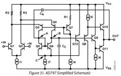
Cn is the optional, external distortion cancellation or "neutralization" capacitor so it is not shown on the AD797 internal schematic. The pin to connect it is at the base of Q15.
C2 is the compensation capacitor, equivalent to Cc from your picture.
Best wishes
David
Last edited:
The (almost) full schematic is http://www.diyaudio.com/forums/solid-state/119793-ad797-guts.html#post1461885
David
Is there a SPICE file around here for the AD797 guts?
And, while I understand that the physics prevents accurately complementary devices, symmetry does look nice.
Me too, it seems people are a bit hesitant to post before they read his comments.
Best wishes
David
I don't think I ever got past some preliminary ideas, but I can take a look. One big problem was that I lost lots of hobby work when my disk crashed and the IT department found a ransomware virus in my personal files and refused to backup most of them.
Dimitri D. took one of the discrete op-amps from a thread here and went all the way to stuffed boards. The data looks nice but I don't know where it is going to be published. This one is JFET fully complementary.
Scott, thanks for the search, a pity if some work has been lost.
I want low noise but the main interest was to learn how the ideas of the AD797 could be applied to a fully complementary circuit.
In particular the AD797 distortion reduction, which I see as two related ideas - the driven current mirror and the distortion "neutralization" connection.
I can't really see how to implement two floated current mirrors.
I would be very interested to see even an outline of your concept, if you come across any old notes or it comes to mind.
I am surprised that no one else seems to have run with the ideas in the AD797 when it clearly works so well.
Best wishes
David
...You can parallel an extra pair of input devices of the same type if you just want a noise improvement.
I want low noise but the main interest was to learn how the ideas of the AD797 could be applied to a fully complementary circuit.
In particular the AD797 distortion reduction, which I see as two related ideas - the driven current mirror and the distortion "neutralization" connection.
I can't really see how to implement two floated current mirrors.
I would be very interested to see even an outline of your concept, if you come across any old notes or it comes to mind.
I am surprised that no one else seems to have run with the ideas in the AD797 when it clearly works so well.
Best wishes
David
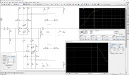
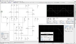
David, here is my take on the concept you're talking about (I believe ) - simplified simulation.
Two current mirrors (top and bottom) at the output, driven at 4 points (all 4 emitters) as folded cascodes.
The thing is rather linear and fast at the same time, easily showing 400V/uS slew rate as is. It works pretty well even with resistors in place of the CCSs.
For practical use, it should be supplied with the fast output buffer.
Also - if we replace those simple mirrors with more accurate cascoded ones, like the ones I used in Lichtstark - the thing will become even more fast and linear.
What do you think? Is that what you're looking for?
Cheers,
Valery
) - simplified simulation.Two current mirrors (top and bottom) at the output, driven at 4 points (all 4 emitters) as folded cascodes.
The thing is rather linear and fast at the same time, easily showing 400V/uS slew rate as is. It works pretty well even with resistors in place of the CCSs.
For practical use, it should be supplied with the fast output buffer.
Also - if we replace those simple mirrors with more accurate cascoded ones, like the ones I used in Lichtstark - the thing will become even more fast and linear.
What do you think? Is that what you're looking for?
Cheers,
Valery
Attachments
- Status
- This old topic is closed. If you want to reopen this topic, contact a moderator using the "Report Post" button.
- Home
- Amplifiers
- Solid State
- Fully complementary AD797?