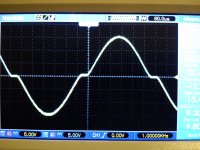
hi all, i have build my first tube amp, and have this issue shown in the pic.
it starts at about 7.5-8 watts output, gets worse until clipping at about 20 watts (Ultralinear)
it's a class AB1 PP amp with a pair of el34s for each channel, 3.6k//6 UL OPTs, with 2 12AT7s per channel, one as gain stage (in parallel), one as LTP phase inverter (it uses 12AX7 originally, but the ones i have atm are no good).
B+ is 440v, cathode bias, with separate resistor for each tube (900ohm +470uF bypass).
at the moment it's biased at about 37mA idle, about 60% plate dissipation.
1. is it's power output where it should be? (i was expecting more tbh)
2. any ideas how i can eliminate crossover distortion?
(i got the feeling biasing won't help here)
thanks for your time")
it starts at about 7.5-8 watts output, gets worse until clipping at about 20 watts (Ultralinear)
it's a class AB1 PP amp with a pair of el34s for each channel, 3.6k//6 UL OPTs, with 2 12AT7s per channel, one as gain stage (in parallel), one as LTP phase inverter (it uses 12AX7 originally, but the ones i have atm are no good).
B+ is 440v, cathode bias, with separate resistor for each tube (900ohm +470uF bypass).
at the moment it's biased at about 37mA idle, about 60% plate dissipation.
1. is it's power output where it should be? (i was expecting more tbh)
2. any ideas how i can eliminate crossover distortion?
(i got the feeling biasing won't help here)
thanks for your time
Attachments
nikk,
How did you come up with a 900 ohm cathode resistor for each EL34? This value sounds way to high. I looked at a couple of datasheets and it looks like a cathode value of 130 ohms is what they specify. In this setup they are saying plate current should be more like 95ma. and screen current 22ma. All of which should give you closer to 35 watts with 3.6k output transformer. I would get the bias up where it belongs and see if the cross over distortion simply goes away.
Mickeystan
It happens because grid currents are non-linear, and when the voltage approaches zero volt they get increased.
Your picture shows that your amp decided to be class AB1 up to 7.5-8 Watt, then coupling capacitors charge increasing the bias voltage, so you are getting class C above 7.5-8W. Or do you have cathode bias? The same story...
Your picture shows that your amp decided to be class AB1 up to 7.5-8 Watt, then coupling capacitors charge increasing the bias voltage, so you are getting class C above 7.5-8W. Or do you have cathode bias? The same story...
First off your bias is too low. That 900 ohm would be okay if it was shared by both tubes. Use a 470 ohm and see where that gets you. The second thing that is happening is the 470ufd cap is charging with the signal and it can't discharge fast enough so the outputs temporarilly are cut off. Make that cap smaller 100ufd should be sufficient. You will see the crossover disappear.
nikk,
How did you come up with a 900 ohm cathode resistor for each EL34? This value sounds way to high...
Mickeystan
It happens because grid currents are non-linear...
First off your bias is too low. That 900 ohm would be okay if it was shared by both tubes...
900ohm too high? i must have misunderstood something.
it's cathode bias, originally 500ohm were shared between both tubes, i changed that to 900ohms each (a bit hotter than the original).
according to this, it's at ~60% plate dissipation, a 470ohm resistor would bring that to over 100% idle?
what am i missing here?
(i will try smaller bypass caps, i have a few 100uFs)
> AB1 PP amp with a pair of el34s.., 3.6k//6 UL OPTs, ...B+ is 440v, cathode bias...
Cathode bias is really class A. It can be "forced" to AB, but you typically get the crossover you are seeing.
Your load is too low for the idle current you are at.
If you increase the idle current to cover a 3.6K load, the poor EL34s will melt.
> i was expecting more tbh
Class A is nominally 50% efficient. In real life we observe 45%-65%, but call it 50%.
So to get power out you MUST idle at large power.
A max-power self-bias design will aim for 99% of plate rating. Say EL34 is good for 25W/plate. Then a pair is 50W dissipation. 50% efficiency gives 25W output. You would be in that zone, if the crossover were acceptable.
In hi-fi it may be. Your average will be far below 20W output. The peaks to 20W transient will be too short to majorly change the bias. You will not have such gross crossover on speech/music as you do on steady tone.
I happen to know a very happy A condition for two EL34 at 400V and 20W per plate. Use 6.6K load, 250r common cathode, a few K in G2. This gives 19W-20W easily and conservatively (and visibly clean with no NFB). This would be 24W at 440V and 24W-25W per plate.
So your Rk is about 1.8X too big, and your Rload is about 1.8X too low.
EL34 data, page 5, shows 3.4K load with self-bias using 350V supply and giving 35W output. Common cathode resistor 130 Ohms. You could get here with a big power B+ drop resistor running near 22 Watts (so a 50W part, per channel). That seems wasteful.
Since this 3.6K is in your hand, and does not offer a choice of secondary impedances(?), I would change over to fixed-bias. A pair EL34 will pull 3.6K OK, and at 440V will give near 50 Watts output.
Dont forget when you calculate plate dissipation to use plate to cathode voltage not plate to ground. Also deduct screen current.
i keep that in mind, thanx.
> AB1 PP amp with a pair of el34s.., 3.6k//6 UL OPTs, ...B+ is 440v, cathode bias...
Cathode bias is really class A. It can be "forced" to AB, but you typically get the crossover you are seeing.
Your load is too low for the idle current you are at.
If you increase the idle current to cover a 3.6K load, the poor EL34s will melt.
> i was expecting more tbh
Class A is nominally 50% efficient. In real life we observe 45%-65%, but call it 50%.
So to get power out you MUST idle at large power.
A max-power self-bias design will aim for 99% of plate rating. Say EL34 is good for 25W/plate. Then a pair is 50W dissipation. 50% efficiency gives 25W output. You would be in that zone, if the crossover were acceptable.
In hi-fi it may be. Your average will be far below 20W output. The peaks to 20W transient will be too short to majorly change the bias. You will not have such gross crossover on speech/music as you do on steady tone.
I happen to know a very happy A condition for two EL34 at 400V and 20W per plate. Use 6.6K load, 250r common cathode, a few K in G2. This gives 19W-20W easily and conservatively (and visibly clean with no NFB). This would be 24W at 440V and 24W-25W per plate.
So your Rk is about 1.8X too big, and your Rload is about 1.8X too low.
EL34 data, page 5, shows 3.4K load with self-bias using 350V supply and giving 35W output. Common cathode resistor 130 Ohms. You could get here with a big power B+ drop resistor running near 22 Watts (so a 50W part, per channel). That seems wasteful.
Since this 3.6K is in your hand, and does not offer a choice of secondary impedances(?), I would change over to fixed-bias. A pair EL34 will pull 3.6K OK, and at 440V will give near 50 Watts output.
so i was right i kept the idle current low?
i got it running with 470ohm/100uF per tube, that's about at max dissipation, i get ~12.4Vrms output before clipping, that's 26.5W.
the plate dissipation is about 31W+, i didn't run it long enought to see any red- plating.
so, if i get this right, if i don't use higher impedance transformer or fixed bias, i'm doomed to crossover distortion or melting tubes?
(only one secondary on the opts)Attachments
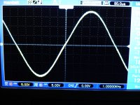
..i got it running with 470ohm/100uF per tube, that's about at max dissipation, i get ~12.4Vrms output before clipping, that's 26.5W. the plate dissipation is about 31W+, i didn't run it long enought to see any red- plating.
At full signal when you get 12,4 Vrms out, not all the DC-power that goes in the EL34 is dissipated in the tube.
Have you taken into account the audio power that you get out from tubes ?
The dissipation under signal condition is the difference between input DC power and output AC power.
At full signal when you get 12,4 Vrms out, not all the DC-power that goes in the EL34 is dissipated in the tube.
Have you taken into account the audio power that you get out from tubes ?
The dissipation under signal condition is the difference between input DC power and output AC power.
so, with the above 26+ watts on the output, each tube's dissipation is 31-13=18w? so it's safe?
please forgive my thickness, i'm having a hard time thinking of this as class A.
what about PRR's post? i'm properly confused.
It is very safe. EL34 can dissipate 25 W at anode and additionally 8 W at g2.
If you have measured the dissipation from cathode current, then that includes both anode- and g2 currents.
Your OPT generates low load impedance. Therefore most linear output signal is achieved at high anode current and near or at max. allowed idle dissipation.
I once tested different (fix bias) PP-topologies, pentode and UL, with EL34 and 4k OPT.
Optimum cathode current with 460 V supply voltage was 60 mA/tube in both cases.
This bias is practically at maximum allowed dissipation.
ok first f all thanx to all for your help, i'm very new at this.
i need to study this more.
so, as long as it's safe and the output power (26w+) is healthy, at least i'll have peace of mind.
i'll fire up the scope and test it some more.
thanx again, any further guidance will be greatly appreciated
i need to study this more.
so, as long as it's safe and the output power (26w+) is healthy, at least i'll have peace of mind.
i'll fire up the scope and test it some more.
thanx again, any further guidance will be greatly appreciated
470 ohms per valve is the normal cathode bias resistor for EL34 in Class AB with an OPT in the region of 5-6k. 900 ohms is far too high (and 135? which someone suggested is far too low). What you are seeing is the bias shift due to second order distortion when signal is present pushing you down into Class C operation.
If you want to run low impedance OPTs then you need to run fixed bias Class B.
If you want to run low impedance OPTs then you need to run fixed bias Class B.
If you want to run low impedance OPTs then you need to run fixed bias Class B.
i was given the opts and schematic by a kind gentleman who definately knows what he's doing. the original schematic used 500ohm shared resistor for both tubes.
i can only think he, by mistake, gave me an other schematic revision, designed for bigger opt impedance.
i'm guessing it's because the opt that i don't get all power i should?
It is difficult to imagine under what conditions a 500 ohm shared resistor would be correct for a pair of EL34. I suspect that the 'kind gentleman' does not know the difference between cathode resistor bias and fixed bias, so designed for the latter but then implemented the former.
For those not in the know, the big difference is that the fixed bias is fixed. That means you can set it to what quiescent bias you want and get the same conditions when signal is present. Cathode resistor bias is not fixed; it moves when some signal arrives (because of second-order distortion in the valve). As a result, you have to bias the valves 'hotter' than you actually want so the shift to 'colder' bias leaves them with the right bias for signal. This works fine for Class A and 'hot' Class AB, as the current (and hence bias) does not change too much (maybe 10%). It fails badly for Class B (or 'cool' Class AB), where the current changes a lot.
For those not in the know, the big difference is that the fixed bias is fixed. That means you can set it to what quiescent bias you want and get the same conditions when signal is present. Cathode resistor bias is not fixed; it moves when some signal arrives (because of second-order distortion in the valve). As a result, you have to bias the valves 'hotter' than you actually want so the shift to 'colder' bias leaves them with the right bias for signal. This works fine for Class A and 'hot' Class AB, as the current (and hence bias) does not change too much (maybe 10%). It fails badly for Class B (or 'cool' Class AB), where the current changes a lot.
what am i missing here?
Bias, independent from signal level.
Actually, such distortions are not called "Crossover". They are called "Farting".
Bias, independent from signal level.
Actually, such distortions are not called "Crossover". They are called "Farting".
i won't ask how it got that namenow that it's "properly" biased, is it going to eat the tubes fast?
it's going to be a big challenge for me to convert it to fixed bias
- Status
- This old topic is closed. If you want to reopen this topic, contact a moderator using the "Report Post" button.
- Home
- Amplifiers
- Tubes / Valves
- crossover distortion and other questions (first timer)