Hi all
I’m working on design of a SRPP output stage using 6N2P tubes with +B 160V to feed a power amp that has 100K potentiometer at the front.
6N2P datasheet: http://www.mif.pg.gda.pl/homepages/frank/sheets/112/6/6N2PEV.pdf
As far as I understand SRPP, the proper Rk values have to be calculated taking into account the load impedance. With 100K load it looks like they need to be quite big.
QUESTION: Can you help me with Rk values calculation that would work for the design? ...OR 100K load is large enough for this SRPP to work Ok with some 'reasonable' Rk. Say around 500 Ohm.
Thanks
PS - I'm not a tube guru, but hopefully understand the basics.
IMHO 160V is too low for a 6N2P, 300V would seem more appropriate. However...
mh-audio.nl - Home
Why SRPP though? How much gain do you really need? Have you considered CCDA instead? It's constant current makes PS noise easy to filter because it "looks" like a resistor to the PS.
John Broskie of Tubecad.com shows the following circuit.
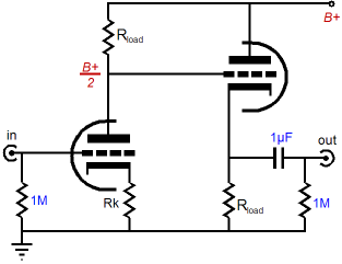
I've used this topology as a preamp and you'll find a 6N1P is probably fine gain wise. (rload 47K rk 240R B+ 250V) Replace the 1M input resistor with a 100K volume pot.
Just an idea...
Cheers.
mh-audio.nl - Home
Why SRPP though? How much gain do you really need? Have you considered CCDA instead? It's constant current makes PS noise easy to filter because it "looks" like a resistor to the PS.
John Broskie of Tubecad.com shows the following circuit.
I've used this topology as a preamp and you'll find a 6N1P is probably fine gain wise. (rload 47K rk 240R B+ 250V) Replace the 1M input resistor with a 100K volume pot.
Just an idea...
Cheers.
Last edited:
> design of a SRPP output stage
Show "your" SRPP.
In another thread the actual topology was uncear and we darted down WAY too many side-paths before the OP figured out what he had done.
> As far as I understand SRPP, the proper Rk values have to be calculated taking into account the load impedance.
Are you reading Broskie? Please cite the essay you are looking at.
> using 6N2P tubes with +B 160V
Assuming "most" of the 160V is split across *two* tubes, that's say 70V per tube.
What current do you want to run?
In "most" tube work, more is good. Broskie has pointed out some quirks in some things often called "SRPP".
I'll dartboard 1mA. Much-much more than your ~~20uA load current, yet not excessive for most tubes.
6N2PEV at 80V and 1mA looks like 0.5V bias. So 500 Ohms.
In hi-Z load you can swing 40V each way, so 2V should be clean.
But I have no idea why you want a tube with Mu=100 in a SRPP in a hi-fi system. Voltage gain will be very high.
Rk in an SRPP performs two roles:
1. biases the valves
2. sets the output impedance and the optimum load impedance (which are almost never the same value), but note that with a 100k load you can probably not worry about either of these
See the Valve Wizard pages for the relevant formulas. Why do you think an SRPP is the right stage? Mu-follower may be better. However, 160V is quite a low rail voltage for any circuit which puts two valves in series.
Thank you all for comments and suggestions. Much appreciated.
Why SRPP? As I mentioned, I’m not a tube guru. Ok, - the story is:
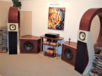
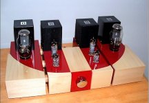
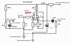
I simply had a chance to listen to 6N2P SRPP output stage working with a tube power amp loaded with horn speakers, and was very impressed with the sound. I do have EL84 based power amp and horn speakers that I built 10 years ago (see attached images). My old CD player had to be replaced, so I decided to build a new one, that would be using TDA1541 DAC. TDA1541 has current output, which will be connected directly to the grid of 6N2P, converting into the voltage on the input 91 Ohm resistor. The signal is quite small, so the high mu tube will help to get proper output.
+160V is simply because of the transformer that I have. One channel current should be around 1.2 mA.
The SRPP design that I now have in mind is on another image.
I read few SRPP articles. The one I liked by Merlin Blencowe is attached as PDF.
Thanks again for your help. I’m learning from your comments : )
Why SRPP? As I mentioned, I’m not a tube guru. Ok, - the story is:
I simply had a chance to listen to 6N2P SRPP output stage working with a tube power amp loaded with horn speakers, and was very impressed with the sound. I do have EL84 based power amp and horn speakers that I built 10 years ago (see attached images). My old CD player had to be replaced, so I decided to build a new one, that would be using TDA1541 DAC. TDA1541 has current output, which will be connected directly to the grid of 6N2P, converting into the voltage on the input 91 Ohm resistor. The signal is quite small, so the high mu tube will help to get proper output.
+160V is simply because of the transformer that I have. One channel current should be around 1.2 mA.
The SRPP design that I now have in mind is on another image.
I read few SRPP articles. The one I liked by Merlin Blencowe is attached as PDF.
Thanks again for your help. I’m learning from your comments : )
Attachments
Last edited:
@ kodabmx re CCDA
Thanks for pointing out and posting the link
The design seams simple and clean, so I'd give it a try and compare to SRPP. ... if SRPP is an option for the situation. Do you think this design will work with 6N2P and B+ 160V? I assume I'd keep Rload and Rk values the same.Have you considered CCDA instead? It's constant current makes PS noise easy to filter because it "looks" like a resistor to the PS.
I've used this topology as a preamp and you'll find a 6N1P is probably fine gain wise. (rload 47K rk 240R B+ 250V)
Thanks for pointing out and posting the link
You're welcome. Keep in mind the schematic I posted leaves out the REQUIRED grid stopper resistors and the safety diode wired from the first tubes plate to the second tubes cathode. This protects the tubes at start up by flowing current around the tube and when the tubes are flowing current it becomes reverse biased and falls out of the circuit. Without it the second tube will have B+ on it's grid at start up and arc over.
More info here: CCDA: constant-current-draw amplifier
If you use a 6N2P in CCDA I'd change rk=820. rload might be better with 75k instead of 47k.
More info here: CCDA: constant-current-draw amplifier
If you use a 6N2P in CCDA I'd change rk=820. rload might be better with 75k instead of 47k.
Last edited:
Thanks
My thoughts regarding the Rk & Rload were: 6N2P has internal resistance around 50K, so to get B+/2 on the second grid you'd need about the same Rload (47K). Am I lost? For Rk I assume that its role is to set the operating point. With 1.2mA current, 820R will set it to -1V. and 400R - to about -0.5V. Correct?
My thoughts regarding the Rk & Rload were: 6N2P has internal resistance around 50K, so to get B+/2 on the second grid you'd need about the same Rload (47K). Am I lost? For Rk I assume that its role is to set the operating point. With 1.2mA current, 820R will set it to -1V. and 400R - to about -0.5V. Correct?
Roughly. I was looking as an OP of 1.25V 1.5ma.
It looks good when I look at the curves: Tube Tester Files - 6N2P - 6H2P
EDIT: I was still working with a 300V B+... Looking at it again the OP would be 0.5ma, 1V so Rload 47k rk 200r or so.
Anyone with more experience want to weigh in on this?
EDIT2: You could use a voltage doubler on your transformer to get this tube closer to it's ideals... with ~320V I'd use rload 100K, rk 1k.
Last edited:
With voltages that low better use a 6N1P.
Something like this could work.
Mona
Thanks for the suggestion
I need first resistor to be under 100 Ohms.
Nice image editing : )
@ kodabmx
Quite useful article! One thing though. The suggested grid stopper’s value is 300 Ohm. I’m not sure I understand why. It should be capacitance and frequency dependent. Could you explain how they came up with 300 Ohm? … Or what is the practical min value for it? Based on what I’ve seen, it should be higher.
Thanks
Keep in mind the schematic I posted leaves out the REQUIRED grid stopper resistors ...
More info here: https://www.tubecad.com/2009/03/blog0161.htm
Quite useful article! One thing though. The suggested grid stopper’s value is 300 Ohm. I’m not sure I understand why. It should be capacitance and frequency dependent. Could you explain how they came up with 300 Ohm? … Or what is the practical min value for it? Based on what I’ve seen, it should be higher.
Thanks
300 is good enough from my findings... I've only seen higher than 1k in instrument amps.
Practical minimum is 100 ohm for me. You can ask him. He's pretty at responding to email...
sales@glass-ware.com
Practical minimum is 100 ohm for me. You can ask him. He's pretty at responding to email...
sales@glass-ware.com
> chance to listen to 6N2P SRPP output stage working with a tube power amp loaded with horn speakers, and....
I was very impressed by a recent drive in a Hyundai, so I got a gear shift knob made the same way.
Objectively, we do not know if the gear knob, or the SRPP, really had much to do with the total engine/tire or amp/horns performance.
But this plan, with some mods, is not "wrong".
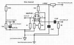
I do think the tube you propose is MUCH too much gain for a hi-fi, unless you are using it some strange way. Also that 91 Ohm input is very strange. Is this maybe a follower for a naked DAC chip? That needs a special form of amplifier, much study of how it handles un-filtered digital glitching.
See attached sketch. Estimated performance:
160V supply
With fat 12AX7 types:
current about 0.9mA
Gain = 48 into 100Meg
Gain = 41 into 100K
Gain = 24 into 15K
Zout about 15K
-3dB @ 400KHz
THD 0.15% @ 2V peak output (50mV peak input)
with 12AU7-types:
current about 4mA
Gain = 10 into 100K
Zout about 4K
THD 0.2% @ 2V peak output (200mV peak input)
THD 3% @ 35V(!) peak output
I was very impressed by a recent drive in a Hyundai, so I got a gear shift knob made the same way.
Objectively, we do not know if the gear knob, or the SRPP, really had much to do with the total engine/tire or amp/horns performance.
But this plan, with some mods, is not "wrong".
I do think the tube you propose is MUCH too much gain for a hi-fi, unless you are using it some strange way. Also that 91 Ohm input is very strange. Is this maybe a follower for a naked DAC chip? That needs a special form of amplifier, much study of how it handles un-filtered digital glitching.
See attached sketch. Estimated performance:
160V supply
With fat 12AX7 types:
current about 0.9mA
Gain = 48 into 100Meg
Gain = 41 into 100K
Gain = 24 into 15K
Zout about 15K
-3dB @ 400KHz
THD 0.15% @ 2V peak output (50mV peak input)
with 12AU7-types:
current about 4mA
Gain = 10 into 100K
Zout about 4K
THD 0.2% @ 2V peak output (200mV peak input)
THD 3% @ 35V(!) peak output
Attachments
Last edited:
PRR also put 470k as grid leak at the input, but;
The 12AX7 proposal from PRR is a solution then.
Mona
So i suppose it is a charge for a DAC and you need considerable gain.Thanks for the suggestion
I need first resistor to be under 100 Ohms.
Nice image editing : )
The 12AX7 proposal from PRR is a solution then.
Mona
The grid stopper resistors should be carbon composition. Metal film resistors don't seem to work. The grid stoppers are mandatory to prevent self oscillation....
I always use metal film with no problems... Interesting.
- Status
- This old topic is closed. If you want to reopen this topic, contact a moderator using the "Report Post" button.
- Home
- Amplifiers
- Tubes / Valves
- SRPP preamp - Rk calculation