There is an index of apex amplifiers thread created by xrk971. Very useful in finding the final design.
My findings/ guesses on nomenclature
AX for class AB with bjt,
AA for class A with bjt
FX for MOSFET o/p class AB
SR for studio reference with bjt class AB
FR for studio reference with MOSFET class AB
The number generally denotes the no of transistors or it can denote the power o/p.
Well, that's as far as I can guess..
Reg
Prasi
There is an index of apex amplifiers thread created by xrk971. Very useful in finding the final design.
My findings/ guesses on nomenclature
AX for class AB with bjt,
AA for class A with bjt
FX for MOSFET o/p class AB
SR for studio reference with bjt class AB
FR for studio reference with MOSFET class AB
The number generally denotes the no of transistors or it can denote the power o/p.
Well, that's as far as I can guess..
Reg
Prasi
Thank you for the clarification Prasi
There is an index of apex amplifiers thread created by xrk971. Very useful in finding the final design.
My findings/ guesses on nomenclature
AX for class AB with bjt,
AA for class A with bjt
FX for MOSFET o/p class AB
SR for studio reference with bjt class AB
FR for studio reference with MOSFET class AB
The number generally denotes the no of transistors or it can denote the power o/p.
Well, that's as far as I can guess..
Reg
Prasi
Thanks! I have used this info to organize my folders of images a bit. However this leaves out a few series: A, BA, BG, BX, CA, F, FA, FH, GA, H, HX, MM, NX, P
...any guidance on these?
That leaves out not few, but many!. Only Mr. Mile can clarify.Thanks! I have used this info to organize my folders of images a bit. However this leaves out a few series: A, BA, BG, BX, CA, F, FA, FH, GA, H, HX, MM, NX, P
...any guidance on these?
Reg
Prasi
Apex AA14 just a quick draft as I had a moment today. not yet optimized, for comments. its late here, almost 1.00AM
reg
Prasi
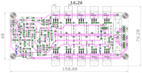
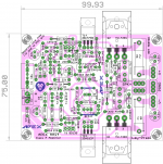
Here is a much more refined layout for AA14... 'Ultimate Fidelity' in Class-A?

reg
Prasi
Attachments

Last edited:
hi mr miles, sorry for jumping the thread but i wasnt getting the help i desperately need in the other thread which i guess you're not frequenting so here i am.
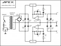
i built your psu-5 according to the post, and it works, sounds wonderful but the voltage drop is 8v from input to output.
how can i lower the voltage loss to make it more economical?
i changed the 12v zener to an led and it only lowered the voltage loss 1v or so.
thanks.
http://www.diyaudio.com/forums/solid-state/173462-studio-reference-amplifier-2.html#post2305431
hi mr miles, sorry for jumping the thread but i wasnt getting the help i desperately need in the other thread which i guess you're not frequenting so here i am.
i built your psu-5 according to the post, and it works, sounds wonderful but the voltage drop is 8v from input to output.
how can i lower the voltage loss to make it more economical?
i changed the 12v zener to an led and it only lowered the voltage loss 1v or so.
thanks.
http://www.diyaudio.com/forums/solid-state/173462-studio-reference-amplifier-2.html#post2305431
See post #18 of the Studio Reference amplifier.
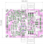
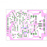
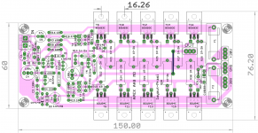
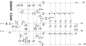
AA9MD (Multiple Output Device)
AA9 MD layout..
Attachments
Last edited:
AA9 MD layout..
too late to edit, but here is the consideration.
I could have avoided the jumper for feedback but i want to take it right from the output connector...
Also it is possible to increase the distance between bdw's, but pcb would become too large...
also i kept the width of pcb as small as possible so that a 2U (ideal 3U and above) cabinet could be used to build the amp with adequate heat sinking..Pl confirm Mr. Mile..
reg
Prasi
Last edited:
Attachments
Here is a much more refined layout for AA14... 'Ultimate Fidelity' in Class-A?
reg
Prasi
Beautiful work there Prasi.

May we please have PDFs for home etching?
Thanks!
Beautiful work there Prasi.
May we please have PDFs for home etching?
Thanks!
Thanks X. here are all the files and gerbers for APEX AA14 Class A Amp.
reg
Prasi
Attachments
too late to edit, but here is the consideration.
I could have avoided the jumper for feedback but i want to take it right from the output connector...
Also it is possible to increase the distance between bdw's, but pcb would become too large...
also i kept the width of pcb as small as possible so that a 2U (ideal 3U and above) cabinet could be used to build the amp with adequate heat sinking..Pl confirm Mr. Mile..
reg
Prasi
Here are the pdf files for AA9MD and gerbers.
reg
Prasi
Attachments
Last edited:
Thanks X. here are all the files and gerbers for APEX AA14 Class A Amp.
reg
Prasi
Sweet!
Thanks, Prasi. I assume this means your Eagle PC is up and working again?
Very nice layout, interesting schematic thank you!
My question do the power darlingtons need to matched (usually when we use multiple power semis need some matching)
If yes how we can do that?
If I do not find BDW darlingtons can I (we) use the more available TIP142 & 147 here in N. America
Thank you
My question do the power darlingtons need to matched (usually when we use multiple power semis need some matching)
If yes how we can do that?
If I do not find BDW darlingtons can I (we) use the more available TIP142 & 147 here in N. America
Thank you
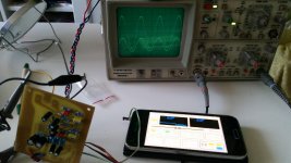
Apex TB1
I know I messed up a little with pcb, but Mr. Apex's TB1 works perfectly. Frequency from 5Hz up to 17kHz with absolutely no distortion, perfect sine. I don't have a proper signal generator, so I use my phone as it. All wirings are temporary. I'll post again when I connect it properly.
Thanks Apex for Your great contribution in DIY.
Attachments
Hi Gabor,Very nice layout, interesting schematic thank you!
My question do the power darlingtons need to matched (usually when we use multiple power semis need some matching)
If yes how we can do that?
If I do not find BDW darlingtons can I (we) use the more available TIP142 & 147 here in N. America
Thank you
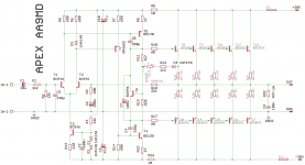
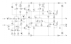
AA9MD has the same sch as AA9 posted few posts ago except for o/p stage. And AA9 has TIP142,147 as o/p .
You could take a look at that.
Also BDW are available in mouser.
Although Mr. Mile can answer, but I think his ckts rarely call for matched transistors especially o/p.
The large emitter resistors would also help in this regard.
An eBay transistor testing ckt might work, although to be honest I have not tested a Darlington transistor on it.
Reg
Prasi
Last edited:
Line Preamp
Hi, I did not find the P6 Line Preamp PCB...Has anyone done?
I know I messed up a little with pcb, but Mr. Apex's TB1 works perfectly. Frequency from 5Hz up to 17kHz with absolutely no distortion, perfect sine. I don't have a proper signal generator, so I use my phone as it. All wirings are temporary. I'll post again when I connect it properly.
Thanks Apex for Your great contribution in DIY.
Nice work, did you use loudness switch?
Regards
- Home
- Amplifiers
- Solid State
- 100W Ultimate Fidelity Amplifier