A big thanks to the mods for splitting this post off for me from the other DIY differential probe thread! ") My goal with this differential probe is a bit different, not looking at audio signals but rather looking for oscillating op-amps at low levels. Hence the high(er) frequency range.
My goal with this differential probe is a bit different, not looking at audio signals but rather looking for oscillating op-amps at low levels. Hence the high(er) frequency range.
**********************************
I got fed up with the Rigol and just bought one of the new 300MHz 10-bit ADC Rohde & Schwarz RTB2004 scopes on an intro special they had. But... the optional (comes with passive probes) 200MHZ active probe is listed at $1,920 and the 1.5GHz probe is $4,555. Yeah, that's not going to happen.
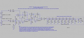
I've been studying this from Linear Tech, an oscilloscope differential probe circuit using their FET-input 4GHz LTC6268-10 chip:
Solutions - LTC6268-10 Oscilloscope Differential Probe
They appear to be attenuating the input signal by 100x, then bumping it back up by 100x (each stage is 10x, the chips are voltage gain >10 stable, decompensated op-amps). The writeup is below the circuit in the link, they say the attenuation is "to allow wide common mode swings".
I see that chip comes in two versions. The LTC6268/LTC6269, which is 500MHz (compensated, unity gain stable apparently)
http://cds.linear.com/docs/en/datasheet/62689f.pdf (opens PDF datasheet)
and the decompensated LTC6268-10/LTC6269-10, which is 4GHz, and is the chip they used in the differential probe circuit
http://cds.linear.com/docs/en/datasheet/626810f.pdf
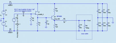
Making the thing especially nice is they have a fully built up LTSpice model ready to go. Scroll down below the photo of their prototype in that first link, the software section. If you have LT spice loaded it comes right up and will run. I'm especially impressed at their efforts to model the coax cable and scope input! In this case it is exactly what I'm looking for, a 1 meg input, since the crazy R&S doesn't have 50R input mode. Go figure.
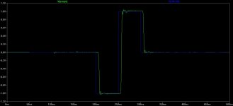
Below is the sim result. The green is the output of the probe circuit into the scope. The blue is a difference plot from +IN to -IN (in LTSpice click on the +IN, then hold down shift and drag to -IN, then release). 100ns period here, so 100MHz.
The circuit is powered by a single 9V battery - shown under the prototype board in their photo - which then goes into that LT1761-5 5V regulator. LOL, that is another thing, R&S shows a "probe power supply" for $1,120. Not clear to me if it would be needed with their probe, but I would guess so.
The LTC6268-10 chips are $7 at Digikey and in stock. Even better, they are available in the larger (easy to solder!) SOIC-8, as well as the TSOT-23-6. They also have the 500MHz LTC6268 version in stock for $7.
I'm probably going to whip up a PC board to see how badly it oscillates! Maybe try the 500Mhz LTC6268s first. I can't even imagine trying to get a layout that would prevent a 4GHz chip from oscillating. The 500MHz chip also has harmonic distortion numbers and a graph in the middle of datasheet page 9. -100dB at 100KHz for the 2nd and 3rd, the lowest it shows, flat to 1MHz, then up to -80dB at 10MHz.
My goal with this differential probe is a bit different, not looking at audio signals but rather looking for oscillating op-amps at low levels. Hence the high(er) frequency range.**********************************
I got fed up with the Rigol and just bought one of the new 300MHz 10-bit ADC Rohde & Schwarz RTB2004 scopes on an intro special they had. But... the optional (comes with passive probes) 200MHZ active probe is listed at $1,920 and the 1.5GHz probe is $4,555.
Yeah, that's not going to happen.I've been studying this from Linear Tech, an oscilloscope differential probe circuit using their FET-input 4GHz LTC6268-10 chip:
Solutions - LTC6268-10 Oscilloscope Differential Probe
They appear to be attenuating the input signal by 100x, then bumping it back up by 100x (each stage is 10x, the chips are voltage gain >10 stable, decompensated op-amps). The writeup is below the circuit in the link, they say the attenuation is "to allow wide common mode swings".
I see that chip comes in two versions. The LTC6268/LTC6269, which is 500MHz (compensated, unity gain stable apparently)
http://cds.linear.com/docs/en/datasheet/62689f.pdf (opens PDF datasheet)
and the decompensated LTC6268-10/LTC6269-10, which is 4GHz, and is the chip they used in the differential probe circuit
http://cds.linear.com/docs/en/datasheet/626810f.pdf
Making the thing especially nice is they have a fully built up LTSpice model ready to go. Scroll down below the photo of their prototype in that first link, the software section. If you have LT spice loaded it comes right up and will run. I'm especially impressed at their efforts to model the coax cable and scope input! In this case it is exactly what I'm looking for, a 1 meg input, since the crazy R&S doesn't have 50R input mode. Go figure.
Below is the sim result. The green is the output of the probe circuit into the scope. The blue is a difference plot from +IN to -IN (in LTSpice click on the +IN, then hold down shift and drag to -IN, then release). 100ns period here, so 100MHz.
The circuit is powered by a single 9V battery - shown under the prototype board in their photo - which then goes into that LT1761-5 5V regulator. LOL, that is another thing, R&S shows a "probe power supply" for $1,120.
Not clear to me if it would be needed with their probe, but I would guess so.The LTC6268-10 chips are $7 at Digikey and in stock. Even better, they are available in the larger (easy to solder!) SOIC-8, as well as the TSOT-23-6. They also have the 500MHz LTC6268 version in stock for $7.
I'm probably going to whip up a PC board to see how badly it oscillates!
Maybe try the 500Mhz LTC6268s first. I can't even imagine trying to get a layout that would prevent a 4GHz chip from oscillating. The 500MHz chip also has harmonic distortion numbers and a graph in the middle of datasheet page 9. -100dB at 100KHz for the 2nd and 3rd, the lowest it shows, flat to 1MHz, then up to -80dB at 10MHz.Attachments
Last edited:
I've started to lay this probe out. To use the compensated LTC6268 vs the uncompensated LTC6268-10, in the Linear Tech app note, I'm probably going to change the values. Instead of the 100:1 attenuator followed by the two 10x voltage gain stages probably 4:1 attenuation followed by two 2x gain stages. Should be less noise. Could do just one 4x gain stage, but this way the layout would work for either chip, just different part values soldered in.
Interesting project!
My hopefully constructive remarks:
- You do not need an active probe for 100-200 MHz, IF you measure at a low
impedance point (e.g. Opamp output)
- You do not need a differential probe for this application,
active single ended < 1GHz is cheap on Ebay
- You can build a simple voltage divider probe: 500 Ohm R into 50 Ohm Coax cable => very high bandwidth
- Your impedance niveau seems too high, go as low as possible
- Forget the sim results above 100 MHz. Not realistic without parasitics.
- The coax cable is the most "ideal" element. Forget the L-C sections and use 50 Ohm
or the LTSpice builtin transmission lines.
- The input divider NEEDS a capacitive too (even at high audio frequencies)
Udo
Last edited:
udok - thanks for the feedback!
Yeah I was wondering myself why they didn't just use a transmission line construct. Seemed to recall Spice had that.
I agree that a passive probe should do the job below 200MHz. The scope comes with some fairly good passive probes, 300MHz on 10:1, 12pF. More than anything I'm just curious what differences the active probe will show, if any.
Good thought about active single-ended probes! I hadn't thought about that. I'll take a look out on eBay.
Definitely agree about the lack of accuracy of the sim at high frequency. The model would need some actual measured parasitic values added all over the place to come up with something approaching reality. So... I'll just build it and measure!
Please tell me more about your last point, about the input divider. Is that adding a "phantom" capacitor to the Spice model to account for capacitances in the divider?
Thanks again for the comments.
Last edited:
For the divider to work since the shunt R has a shunt C you need a parallel C for the series input resistor to match the chunt C. Early probes used a piston trimmer effect where the outside of the probe body screwed up and down to add C. Later ones use a fixed C and a shunt C trimmer in parallel with the load.
Probing above 100 MHz sets you up for many challenges. A ground clip is usually too long for example. The probe capacitance can significantly alter the circuit behavior which is why you want high Z low C probes (enter the active probe). Then you need to check everything to make sure its not lying to you. I have some very fast pulse generators for this purpose (500 pS and 30 pS). They help a lot when making sure its all real. They seem to be hard to find on ebay now. Here is an article on the one I have: http://www.novatech-instr.com/PDF_files/mts529r-2.pdf
Probing above 100 MHz sets you up for many challenges. A ground clip is usually too long for example. The probe capacitance can significantly alter the circuit behavior which is why you want high Z low C probes (enter the active probe). Then you need to check everything to make sure its not lying to you. I have some very fast pulse generators for this purpose (500 pS and 30 pS). They help a lot when making sure its all real. They seem to be hard to find on ebay now. Here is an article on the one I have: http://www.novatech-instr.com/PDF_files/mts529r-2.pdf
For the divider to work since the shunt R has a shunt C you need a parallel C for the series input resistor to match the chunt C. Early probes used a piston trimmer effect where the outside of the probe body screwed up and down to add C. Later ones use a fixed C and a shunt C trimmer in parallel with the load.
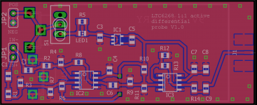
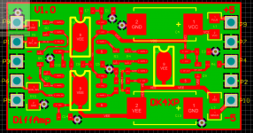
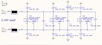
Ah, I understand, thanks. Makes sense. Here is the layout so far, I'll have to think about the best way to add that.
I'm using PC mounted 9V battery snaps under the board rather than the snaps on wire leads that LT has in their photo. The board is the size of the 9V battery, a bit longer in back to mount a card-edge BNC. I'm using a smaller switch - that realtively large toggle they used in the photo is pretty funny.
2 layer board, 28mm x 68mm. A 9V battery is maximum 26.5mm x 48.5mm. JP1 is the probe tips, similar to the LT photo, and JP2 just just a place to test the battery. The front fill and the entire back layer are ground. Vias around the edge and at a few other strategic places to nail them together.No values on the schematic yet, just 0805 sized placeholders, since the value are given in the LT app note for the 6268-10 version. I haven't calculated the new values yet for the compensated 6268 with 4:1 and 4x. I've redrawn the LT circuit and did a renumber, so the part numbering has wound up different than theirs.
Attachments
Last edited:
Can you give a link or describe the set up procedure for the input dividing capacitors?For the divider to work since the shunt R has a shunt C you need a parallel C for the series input resistor to match the chunt C. Early probes used a piston trimmer effect where the outside of the probe body screwed up and down to add C. Later ones use a fixed C and a shunt C trimmer in parallel with the load. .....................
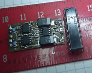
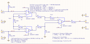
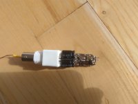
That is how I did it after an Analog Devices data sheet / app note.
I did not need an input divider because my DUTs usually run
on +-5V also. I had to add 3p3 across the feedback Rs or it
would oscillate at 200 MHz. The board is home etched, so
there is no solder mask.
It was an ad-hoc solution. The next version of the DUT had a
built-in test point buffer.
For single ended I use Agilent 1152A probes. Biggest thing
since sliced bread.
Attachments
Last edited:
That is how I did it after an Analog Devices data sheet / app note.
Hey thanks for sharing! The instrumentation amp approach. I probably would have gone that way if I hadn't run into this LT sheet. In the other thread I think there were a few instrumentation amp designs. A good way to go.
Would those 1152A probes work on other scopes? I'll bet they get power from the scope's connector somehow.
Yeah I think the input divider here needs to change. I can see what they did, using 100:1 gives 5V * 100x = 500V, a very typical max input voltage for a general purpose scope. In my case though the target is op-amps in audio circuits, so +/-18Vdc max, 36V rail to rail. I think I'll just move the decimal and set the input range to 50V max. So a 10:1 input divider and 3.2x closed loop gain per stage.
These are FET-input chips and LT really isn't taking advantage of that. The input Z is lower than I would like to see for probing op-amp circuits. I'm going to bump that up.
Hi all,
Very interesting the way this thread points ...
... on & off I've myself been pursuing a couple of "HF probes" for some time now - so inspiring to see that agdr is also considering something similar ...
The probes I have considered are:
1. A wide band-width probe (appr. 1 GHz) which would allow me to look at higher-speed digital signals while not influencing the circuitry I was measuring.
2. A hopefully "just as wide" band-width probe with significant gain (preferably x100 ) which would allow me to look mainly at PSU noise in digital circuitry so as to identify and possibly amend the noise spuriae that the probe would identify.
Ad. 1: I've made the attached circuitry which sims virtually straight to ~ 1.1 GHz - i.e. when not connected to the coax cable going to the oscilloscope. When adding the 50 ohm output resistor and considering the oscillope's appr. 15 pf input capacitance and the typical coax cable's appr. 50 pf/half meter the bandwidth is significantly reduced (only ~ 50 MHz) ... I wonder if something similar won't happen to the probe that agdr is designing ... ?
Ad. 2: Basically the same issue with bandwidth limitation due to the coax cable and input capacitance on the scope seems to exist when considering an amplifying probe. Of course there may also be other challenges trying to amplify e.g. 200 MHz signals - but what to do about the cable issue ... any of you can say what is normally done when transmitting such wideband signals to the oscilloscope in a way that HF cut-off does not happen?
Looking forward to seeing where this goes
Cheers,
Jesper
P.S.: I've traced the PCB in the link 1audio provided in Adobe Illustrator - so if one of you are interested in a reasonable PCB layout copy let me know.
Very interesting the way this thread points ...
... on & off I've myself been pursuing a couple of "HF probes" for some time now - so inspiring to see that agdr is also considering something similar ...
The probes I have considered are:
1. A wide band-width probe (appr. 1 GHz) which would allow me to look at higher-speed digital signals while not influencing the circuitry I was measuring.
2. A hopefully "just as wide" band-width probe with significant gain (preferably x100
) which would allow me to look mainly at PSU noise in digital circuitry so as to identify and possibly amend the noise spuriae that the probe would identify.Ad. 1: I've made the attached circuitry which sims virtually straight to ~ 1.1 GHz - i.e. when not connected to the coax cable going to the oscilloscope. When adding the 50 ohm output resistor and considering the oscillope's appr. 15 pf input capacitance and the typical coax cable's appr. 50 pf/half meter the bandwidth is significantly reduced (only ~ 50 MHz) ... I wonder if something similar won't happen to the probe that agdr is designing ... ?
Ad. 2: Basically the same issue with bandwidth limitation due to the coax cable and input capacitance on the scope seems to exist when considering an amplifying probe. Of course there may also be other challenges trying to amplify e.g. 200 MHz signals - but what to do about the cable issue
... any of you can say what is normally done when transmitting such wideband signals to the oscilloscope in a way that HF cut-off does not happen? Looking forward to seeing where this goes
Cheers,
Jesper
P.S.: I've traced the PCB in the link 1audio provided in Adobe Illustrator - so if one of you are interested in a reasonable PCB layout copy let me know.
Attachments
It seems Novatech stopped making the gadget some time ago. While not perfect its more than adequate for anything I deal with that can be looked at with a scope.
On the preamp for high frequency stuff figure the scope is 50 Ohms input Z. Also the FET has pretty high input C for this application. Usually you are looking for low C so you want a different class of FET something like a J310. One I saw fabricated for a wafer prober in the 1970's used a dual gate mosfet. There are others here who would have even better suggestions. For audio I would cascode it to reduce the input C. I don't think that would work at 1 GHz.
I think the best way forward would be to download older TEK probe manuals for active probes. They have good details on circuit design and construction .The technology is fundamentally the same just more, better and smaller parts today. There are HP manuals as well.
It seems Novatech stopped making the gadget some time ago. While not perfect its more than adequate for anything I deal with that can be looked at with a scope.
Tek had one that used a charged line and reed switch, 25pS rise time pulses in 1963. You might want to explore the SDXXX series DMOS FET's for fast very high impedance applications.
Tek had one that used a charged line and reed switch, 25pS rise time pulses in 1963.
I have one of those somewhere as well. I used it last with the Tek P6013 and P6015 HV probes to check the compensation. Needed it for the higher voltage. Interesting bit of electromechanical construction. Did not look easy to duplicate.
udok - thanks for the feedback!
Yeah I was wondering myself why they didn't just use a transmission line construct. Seemed to recall Spice had that.
I agree that a passive probe should do the job below 200MHz. The scope comes with some fairly good passive probes, 300MHz on 10:1, 12pF. More than anything I'm just curious what differences the active probe will show, if any.
Good thought about active single-ended probes! I hadn't thought about that. I'll take a look out on eBay.
Definitely agree about the lack of accuracy of the sim at high frequency. The model would need some actual measured parasitic values added all over the place to come up with something approaching reality. So... I'll just build it and measure!
Please tell me more about your last point, about the input divider. Is that adding a "phantom" capacitor to the Spice model to account for capacitances in the divider?
Thanks again for the comments.
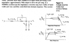
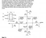
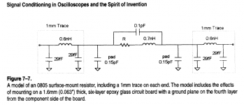
Some good reading about probe basics is in the appendix of AN47 (from Jim Williams) and in "Signal conditioning in oscilloscopes and the spirit of invention" from Steven Roach.
I have attached some informative pictures below.
You will need a network analyzer too, before you can measure (not guessing) something with your probe.
For your original problem of measuring oscillations, a small coil and a spectrum analyzer or a radio detector would be a good solution too.
A big problem with the opamp solutions is slewrate. For example the AD4718 specifies a bandwidth of about 1Ghz, BUT because of the low
slewrate the bandwidth in reality may not be more than 100-200 Mhz.
Udo
Udo
Attachments
Last edited:
Would those 1152A probes work on other scopes? I'll bet they get power from the scope's connector somehow.
...
These are FET-input chips and LT really isn't taking advantage of that. The input Z is lower than I would like to see for probing op-amp circuits. I'm going to bump that up.
I don't think that will work. It doesn't even work with all Agilent scopes that have
these funny BNC + 9 Pin plugs. There seems to be a firmware protocol as there is a least
one scope that recognizes the probe by type and denies to work with it.
The probe has only 100K input resistance, but sports 0.6 pF. It is made for 2.5 GHz
bandwidth after all. The small capacitance makes the ground strap quite harmless.
(High series resonance frequency.)
A better solution might be the 54751A probe. I think it needs only +-15V or so on this
Lemo-like plug, otherwise it it is like the 1152A. I have also used a 1 GHz TEK probe
with external power. But that is officially documented.
Last edited:
Hi again ..
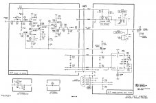
I just did this for a probably relatively simple older tektronix probe - the P6202A (500 MHz bandwidth). And looking at the schematic (image attached) it looks as if - besides various adjustment circuitry - it is mainly source & emitter followers. And the output also is an emitter follower with a bit of compensatory circuitry which feeds directly into a probably relatively long coax cable ...
So I really wonder if there's something I've entirely missed here ... How come they can make the output stage work up till 500 MHz when the coax cable's capacitance and inductance are considered ... ??
This really puzzles me so clarifying input from those of you who know is appreciated
Cheers,
Jesper
I think the best way forward would be to download older TEK probe manuals for active probes.
I just did this for a probably relatively simple older tektronix probe - the P6202A (500 MHz bandwidth). And looking at the schematic (image attached) it looks as if - besides various adjustment circuitry - it is mainly source & emitter followers. And the output also is an emitter follower with a bit of compensatory circuitry which feeds directly into a probably relatively long coax cable ...
So I really wonder if there's something I've entirely missed here ... How come they can make the output stage work up till 500 MHz when the coax cable's capacitance and inductance are considered ... ??
This really puzzles me so clarifying input from those of you who know is appreciated
Cheers,
Jesper
Attachments
Last edited:
@gentlevoice
An ideal BNC cable looks like a 50 ohm resistor, if you terminate it with 50 ohm.
It is not capacitive. I know, this is not easy to understand.
This is because the inductive / length compensates for the capacitive / length.
You need wave theory to fully understand this.
At first here is an incident wave running down the coax and this wave
is reflected at the end, if the coax is not proper terminated.
If the coax is proper terminated with the characteristic impedance,
the incident wave gets absorbed and nothing comes back.
You can easily test this yourself with a few meter coax cable, an oscilloscope and a pulse generator.
The P6202 has a lot of subtle details:
- R17 compensates for the thermal time constant of the Q16A source follower.
- Q16B is a current source, which cancels the offset voltage of Q16A.
The current source ensures that the source follower gain is constant.
- The Q16A input has a negative input resistance, R13-C13 compensates this.
- C12 compensates for the gate capacitance
Bandwidth could be improved by bootstrapping Q16A, but i guess
in practice this could lead to further complications.
Udo
Last edited:
One of the reasons I still keep a TEK 7904A around is for its array of special purpose front-end/plug-in's. Such as the 7A22 diff amp.
If you have a very wide band dual channel scope, why not try using both channel input, with one channel inverted. Make it a diff input. It will track quit well until near the scope BW limits... and you can trim the 10:1 or 100:1 passive high Z probes C to push it as far as possible. Usable for test/trouble-shooting.
-RM
Last edited:
- Status
- This old topic is closed. If you want to reopen this topic, contact a moderator using the "Report Post" button.
- Home
- Design & Build
- Equipment & Tools
- 100MHz+ differential probe