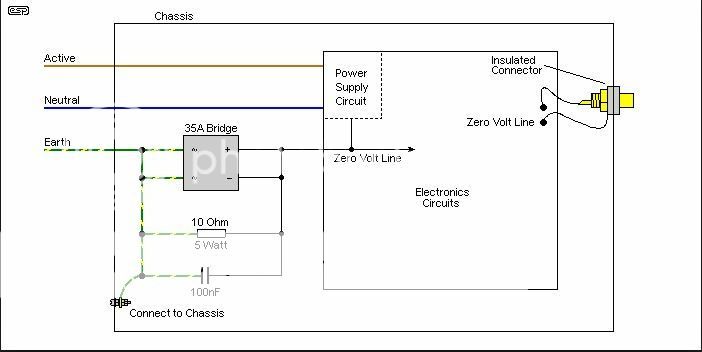
However I would consider the safety risk of a large current surge through this type of connection. I use this type of ground lift, with the chassis (basically the two top plates and foil box lining) connected firmly to mains earth.

Agreed, reversed diodes in parallel are useful for large current shunt. Mainly useful in amps, but in preamps can be omitted
Totally, me too.
There is a great article about grounding on DIYaudio in case people have missed it:
http://www.diyaudio.com/forums/diya...udio-component-grounding-interconnection.html
Cheers, Ale
There is a great article about grounding on DIYaudio in case people have missed it:
http://www.diyaudio.com/forums/diya...udio-component-grounding-interconnection.html
Cheers, Ale
1 wire for signal ground from signal chassis star ground to main star ground on power supply chassis. This includes wires from the 2 filament resistors and the 2 RCA input grounds.
PHP:
I never used this "extra" wire, IMHO it is the source of your ground loop.
Hi Bela?,
The input RCA ground and the filament resistor still must be grounded so are you saying you ground these 2 points at the point where the power supply negative rail is connected to the signal chassis?
Jim
The input RCA ground and the filament resistor still must be grounded so are you saying you ground these 2 points at the point where the power supply negative rail is connected to the signal chassis?
As you can read in my #1280 post the -insulated- input RCA "cold", the grid leak resistor "cold" and the (insulated, the large wattage resistor's heatsink insulated from the resistor pins) filament bias "cold" connected together, this is the input star point. I connect here HT "cold" wire.
Each channel is individual (dual mono).
Connecting the signal star point/s/ to chassis is matter of taste.
Usually the HT "cold" wires connected together in the PSU box, and grounded to PSU chassis.
Sometimes I use "floating" HT, and HT "cold" wires connected together in the PSU box without grounding.
If you connect signal (input) star point to signal chassis, and HT cold wires in the PSU box to chassis (grounding), each additional wire -which is connect together signal and PSU chassis- is the potential source of the ground loop.
And the VT-25 revisited version of the DHT preamp.

http://www.bartola.co.uk/valves/2017/03/12/vt-25-dht-preamplifer/
I'm sure Béla can share his vast experience on this valve. I'm very happy with this version now")
http://www.bartola.co.uk/valves/2017/03/12/vt-25-dht-preamplifer/
I'm sure Béla can share his vast experience on this valve. I'm very happy with this version now

So where are the DHTs then?
It does not matter. I introduced 4P1L for the community in the topic, "One more 4P1L SE". There was no hum problem whatsoever.
As I said, think of currents that flow through wires that have always resistance, and don't mix high dirty and weak input currents on the same wire, and ya'll be happy. Filter capacitors and shunt regulators are the points with minimal dynamic resistances. Close all current loops there. It is simple! And don't invent bicycles with triangle wheels.
I'm very happy with this version now
Once you should try the graphite anode 801.
ppAttachments

I am just starting my first 4p1l dac-output project based on the buffalo iii...finished my utracer...bought a ton of 4p1l and found them varying quiet a bit !!!
May I ask: are there some kind of official numbers for triode and pentode mode testing ? What is considered 100% at which operating point (which should be around 30mA I guess).
Best Regards
May I ask: are there some kind of official numbers for triode and pentode mode testing ? What is considered 100% at which operating point (which should be around 30mA I guess).
Best Regards
4P1L gyrator ltspice sim result, request suggestions
In the process to better understand the gyrator as plate load, I spent some time with LTSpice simulator. I plan to use this as the input stage of a hybrid design.
As it turns out, a 4P1L filament biased at 185 V and 29 ma loaded with a simple single mosfet gyrator yields 0.026% THD with a nice distribution spectra at 10V rms output. Following known rule of thumbs, the IRF710 is biased > 55 ma by the addition of R7. Simulation files are zipped and attached.


However, I noted that the sim shows the need to use very large values for C2 and C3 for reasonable distortion, especially at low frequency. At 20 Hz, when 1 uF is used at C2, H4-9 distortions are around 60 dB higher compared to the 470 uF. Similar thing to a lesser extent happened at C3.
Not quite certain about the finding due to the notorious unreliability of spice in predicting distortion at low level. Furthermore, unable to verify with FFT measurement either due to the required better than -100 dB resolution of analyzer or even sound card not yet available to me. Currently I'm contemplating to build some kind of 20 - 40 dB distortion magnifier for H4 or H5 and higher which is not going to be easy.
Please share your experiences, suggestions and opinions.
In the process to better understand the gyrator as plate load, I spent some time with LTSpice simulator. I plan to use this as the input stage of a hybrid design.
As it turns out, a 4P1L filament biased at 185 V and 29 ma loaded with a simple single mosfet gyrator yields 0.026% THD with a nice distribution spectra at 10V rms output. Following known rule of thumbs, the IRF710 is biased > 55 ma by the addition of R7. Simulation files are zipped and attached.
However, I noted that the sim shows the need to use very large values for C2 and C3 for reasonable distortion, especially at low frequency. At 20 Hz, when 1 uF is used at C2, H4-9 distortions are around 60 dB higher compared to the 470 uF. Similar thing to a lesser extent happened at C3.
Not quite certain about the finding due to the notorious unreliability of spice in predicting distortion at low level. Furthermore, unable to verify with FFT measurement either due to the required better than -100 dB resolution of analyzer or even sound card not yet available to me. Currently I'm contemplating to build some kind of 20 - 40 dB distortion magnifier for H4 or H5 and higher which is not going to be easy.
Please share your experiences, suggestions and opinions.
Attachments
Last edited:
What is the purpose of R4? It's defeating the high impedance of the gyrator and also screwing up your FR. The caps values resulting are too high.
I wouldn't trust much the THD results of the simulations, they give some indication and generally THD is higher than real world.
Here is the response at 9Vrms:

I wouldn't trust much the THD results of the simulations, they give some indication and generally THD is higher than real world.
Here is the response at 9Vrms:
BTW: the screenshots uploaded they don't work
No need for R7 in your circuit, it loads too much the output. R1 and R2 are a pot. C1 isn't needed either. Cascoded pair is better so you can use a high GM and low Crss part (e.g. JFET) by handling the HV by top device.
What is the purpose of R9 and C4?
R10 should be 100k-ish for best noise performance.
HI Ale, thanks for replying so promptly.
I am reposting the screenshots as attachment. Just realized the pics are showing only on Chrome but fail to show on IE and Firefox.
I'll change R10 to 100k. Thanks for catching this.
Now answering your questions. R4 is my attempt to linearize impedance variation of gyrator vs frequency with the price of reduced effective impedance. Should also help reduce H5-9 distortion. Are you sure the loading of R4 will affect FR? Not apparent from the sim to me.
On my sim, the high LF distortions comes with low value of C2, even when R4 is removed. Perhaps I did something wrong with the sim or some other overlooked parameters?
The cascoded gyrators are very good indeed, tried them with 10M45, 2SK170, 2SK117 and 2SK68A for 10ma load and less, still have no BF862 nor J310 to try at higher current.
However, the IRF710 and a family of other TO220 mosfets are also nice provided that they are used at 55ma (for the IRF610, 710, 2SK2013, FQP2N60, 3N60) and up for higher effective gm they can provide. The bias point was suggested by Nelson Pass for the 2SK2013 or IRF610 on the BA3 design and does reduce distortion on all harmonics albeit a few percent. Proven to hold true on other designs as well. For line level input duty, they usually do not sound as mellow compared to the jfets. A bit like a 4P1L compared to a 26.
But I have no experience yet with them as gyrator so I want to evaluate for 20 - 70 ma gyrator since the sim show unbelievably (at least to me) good results. R7 is used to bias the IRF710 at more than 55 ma for higher effective gm. I'll decide on this one through listening, could be that 30 ma bias is already more than enough. Any experience with any of them as gyrator?
R9 and C4 are there just to see the effect of source impedance sometimes required on checks for oscillation, usually helps when some form feedback is involved.
Attachments


Last edited:
Hi Indra
I haven't used the IRF710 on the gyrator myself as I wasn't attracted to its parameters:Crss=6.3pF, Coss=34pF, Ciss=170pF. Despite the 1S@1.2 gfs is attractive, you should expect 160mS at 30mA or 220mS at 60mA.
There are better MOSFETs (albeit lower VDSmax) like the BSH111BK, which is the one I prefer for currents above 25mA which is the limit of the BF862.
The BSH111BK will perform much better:
Crss=1.5pF, Coss=2.7pF, Ciss=19.1pF
gm0=0.64mS @200mA
And the transconductance at operating level is about:'
gm @ 30mA = 250mS
gm @ 60mA = 350mS
As you can see much better than the IRF710.
What is a killer is the HF response due to the parasitic capacitances. If you simulate you will see that the IRF710 will get up to 300kHz (without playing with the load and without adding any CLoad) whereas the BSH111BK up to 4MHz.
On the bench with the BSH111BK and loaded with 100k/220pF I could measure it up to 1.5Mhz. Obviously the rolloff of my measurement buffer and other parasitic capacitances (cable) are playing up, but is darn good!

I'd suggest replacing R7 by a simple CCS to reduce the loading of the gyrator and hence minimising the distortion
Yes, R4 should help taming the high harmonics, but the price you pay is the overall distortion increases.
In your circuit it's about 0.018% @10V. In my version (simulation) of the BSH111BK distortion is 0.005% @10V, or 3 times less.
The higher harmonics are higher in the simulation, but below 100dB, so I don't know whether is worth the trouble in sacrificing overall distortion
See the THD comparison attached.
Again, I don't trust the THD results. I've developed the SPICE models myself, but I mostly get different results in real life.
With regard to the value of C2 and C3 in your circuit, I prefer them to provide a LF rolloff of 5-7Hz and keep the values low (100-200nF). If you look at the THD measurement of Merlin's "Designing High-Fidelity Tube Preamps" there is a great section dedicated to the capacitor distortion. The result is that if you use HV devices, the distortion is lower due to thicker dielectric. I prefer to keep them in lower capacitance value which sound better to my ears.
A 470uF and 100uF /350V parts as C2 and C3 are a rather expensive part in film unless you want to use an electrolytic ( I won't)
If you reduce them to C2=100nF and C3=220nF, response is still unaffected with an LF of 5Hz.
Cheers
Ale
I haven't used the IRF710 on the gyrator myself as I wasn't attracted to its parameters:Crss=6.3pF, Coss=34pF, Ciss=170pF. Despite the 1S@1.2 gfs is attractive, you should expect 160mS at 30mA or 220mS at 60mA.
There are better MOSFETs (albeit lower VDSmax) like the BSH111BK, which is the one I prefer for currents above 25mA which is the limit of the BF862.
The BSH111BK will perform much better:
Crss=1.5pF, Coss=2.7pF, Ciss=19.1pF
gm0=0.64mS @200mA
And the transconductance at operating level is about:'
gm @ 30mA = 250mS
gm @ 60mA = 350mS
As you can see much better than the IRF710.
What is a killer is the HF response due to the parasitic capacitances. If you simulate you will see that the IRF710 will get up to 300kHz (without playing with the load and without adding any CLoad) whereas the BSH111BK up to 4MHz.
On the bench with the BSH111BK and loaded with 100k/220pF I could measure it up to 1.5Mhz. Obviously the rolloff of my measurement buffer and other parasitic capacitances (cable) are playing up, but is darn good!
I'd suggest replacing R7 by a simple CCS to reduce the loading of the gyrator and hence minimising the distortion
Yes, R4 should help taming the high harmonics, but the price you pay is the overall distortion increases.
In your circuit it's about 0.018% @10V. In my version (simulation) of the BSH111BK distortion is 0.005% @10V, or 3 times less.
The higher harmonics are higher in the simulation, but below 100dB, so I don't know whether is worth the trouble in sacrificing overall distortion
See the THD comparison attached.
Again, I don't trust the THD results. I've developed the SPICE models myself, but I mostly get different results in real life.
With regard to the value of C2 and C3 in your circuit, I prefer them to provide a LF rolloff of 5-7Hz and keep the values low (100-200nF). If you look at the THD measurement of Merlin's "Designing High-Fidelity Tube Preamps" there is a great section dedicated to the capacitor distortion. The result is that if you use HV devices, the distortion is lower due to thicker dielectric. I prefer to keep them in lower capacitance value which sound better to my ears.
A 470uF and 100uF /350V parts as C2 and C3 are a rather expensive part in film unless you want to use an electrolytic ( I won't)
If you reduce them to C2=100nF and C3=220nF, response is still unaffected with an LF of 5Hz.
Cheers
Ale
Attachments


Thank you Ale  for sharing your finding with BSH111 and the test mule schematic for higher current loading. You just gave me 2 very valuable solutions in 1 post.
I just realized R6 in your test mule is 10 Meg. No wonder I had nasty distortion on low freq with 3.3 Meg, the cap was overloaded. I'll test with 10 Meg and some other higher values to allow film cap.
I have seen so many variants on the strategy of tweaking an amplifier design in relation to distortion spectra. This time, I put my focus on low h5 and above, especially the odd ones, smoothly cascading whenever possible. I had to trade a bit higher H2 for lower H5 and above. An attempt to (hopefully) avoid an "edgy", "dead" or "mechanical" sound. Using LTSpice only as a rough map (still a noob having just used it for a few months).
I am in the process of tweaking designs on several versions of a 12.5W Class A hybrid amp with a headroom to 55W at Class AB, found feedback related stability issues on some of them. I think the BSH111 is perfect part for gyrator duty for 20-50ma loading. I plan on 4P1L input loaded with bootstrapped gyrator and screen feedback. I attach one of the more stable variant. Will share full detail after successful build.
for sharing your finding with BSH111 and the test mule schematic for higher current loading. You just gave me 2 very valuable solutions in 1 post.I just realized R6 in your test mule is 10 Meg.
No wonder I had nasty distortion on low freq with 3.3 Meg, the cap was overloaded. I'll test with 10 Meg and some other higher values to allow film cap.I have seen so many variants on the strategy of tweaking an amplifier design in relation to distortion spectra. This time, I put my focus on low h5 and above, especially the odd ones, smoothly cascading whenever possible. I had to trade a bit higher H2 for lower H5 and above. An attempt to (hopefully) avoid an "edgy", "dead" or "mechanical" sound.
Using LTSpice only as a rough map (still a noob having just used it for a few months).I am in the
process of tweaking designs on several versions of a 12.5W Class A hybrid amp with a headroom to 55W at Class AB, found feedback related stability issues on some of them. I think the BSH111 is perfect part for gyrator duty for 20-50ma loading. I plan on 4P1L input loaded with bootstrapped gyrator and screen feedback. I attach one of the more stable variant. Will share full detail after successful build.Attachments

- Home
- Amplifiers
- Tubes / Valves
- 4P1L DHT Line Stage