Reviving an old thread gone quiet
But I have a quick question on a current mirror improved with the extra "helper" transistor as in the one posted in post #8. (3 trannies)
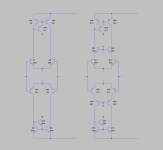
In the context of a symmetric topo with the 2 ltps with their current source, if I need the helper transistor's collector not to be referenced to ground, how is it correctly done?
I would think that just linking up the collectors directly between the 2 opposing helpers would not be a good thing. So what would be the right way?

To the opposite power supply rail.
Using a current mirror with a helper, I thought that, if the VAS also has an helper, it could be a good thing to connect the helpers collectors together and add a local decoupling circuit, limiting the Vce voltage of the helpers.
This could be done on the standard configuration, VAS loaded by a CCS, or a symmetrical configuration, push-pull VAS.
Here (attached) is a simplified illustration to help the discussion.
The situation I'm more interested in, is the cascoded ltp one.
Let's say the rails are at some 60-70V and the Vce0 of the trannies are only 45V, so cascoding the ltp fixes the issue with sharing the rail voltage. The current sources, if using those same trannies would also need to be cascoded, but that's besides the point.
With a situation where the trannies can't handle anywhere near the rail voltage, the mirror's helper can't have its collector sent to the opposite rail, and actually even if it went to the ground, the voltage would be an issue.
If there is cascoding on the ltp, there is a biasing voltage made up to set the cascode o.p, so could that be used for the mirror's helper?
Or would it better to make up a separate biasing network and bias the mirror helpers together but separate from the cascodes, and while at it, would sharing that biasing network with the vas helpers be a good thing?
If the same biasing network is shared by the mirror helper and the vas helper, then wouldn't the vas have some influence on the mirrors?
That schematic is quite simplified, of course there would be resistors added, degen on the ltp and mirrors, a res on the mirror helpers, perhaps base stoppers here and there...
Attachments
The current mirror transistors see very low Vce, usually less than 2VceThe current sources, if using those same trannies would also need to be cascoded, but that's besides the point.
And that is why you should select transistors that have good performance in quasi-saturation. Typically only Low Vce transistors have acceptable quasi-saturation, but you do need to be selective. The BC550c/560c make an excellent CM transistor even when supply rails approach 100V
Last edited:
The current mirror transistors see very low Vce, usually less than 2Vce
For the 2 opposing current mirror parts, yes, but what about the 3rd one, the helper, with its collector usually being tied to ground, will surely see a whole lot more Vce than the other 2.
In the case I'm working on, I need to avoid tying the helper's collector to ground, and with rather high rails, that collector surely can't be going to the opposing rail, so where to tie it then?
With the ltp having a cascode already, with its biasing network in place, wouldn't that biasing network be usable to tie the mirror helper's collector to something that exposes it to less than the rails?
And since the vas stage after that would also have a helper (enhanced vas), plus cascode as well, there would also be a biasing network available, and needed, not just for the vas cascode, but also for its helper's collector.
Would the helper's collector be any disruption to the cascode bias?
If so, then it obviates setting up a separate biasing network for the helpers, and perhaps both helpers, from the mirror and the vas, could share that, if they don't have any influence on each other. If there would be any influence, I suspect it would be more the vas helper having one on the mirror's helper than the other way around.
And that is why you should select transistors that have good performance in quasi-saturation. Typically only Low Vce transistors have acceptable quasi-saturation, but you do need to be selective. The BC550c/560c make an excellent CM transistor even when supply rails approach 100V
Definitely! And those are my choice, with the C pertaining to their gain class and not Cordell
 , even though it would be Cordell's models being used. I would obtain the C suffixed parts when getting the parts for the real build.
Tie A to B in your first diagram and then use a replica of the output signal to drive (bootstrap) the interconnection??
Only thing is there is still GND connection unless driven from the feedback network?
The bootstrap being a res divider somehow?
But then those helpers will "see" nearly the total swing rail to rail, and let's say if the input stages had much lower rails than the outputs, then the boostrapping level taken from the outputs would swing more than the input stage's rails, probably even causing reverse biasing at some point somewhere.
One other aspect comes into play with larger voltage swings, besides the exposition to voltage, for which I'm not sure what the actual effects are, is the early effect. Apparently it doesn't bother current mirrors, as explained by Self, but does this apply to the helper in the mirrors? Would the early effect not become an issue on such large swings?
And then with high rails, the point is to cascode to make use of the low Vce0 higher gain parts, but something must be done as well for those helpers, which aren't cascoded or whatever.

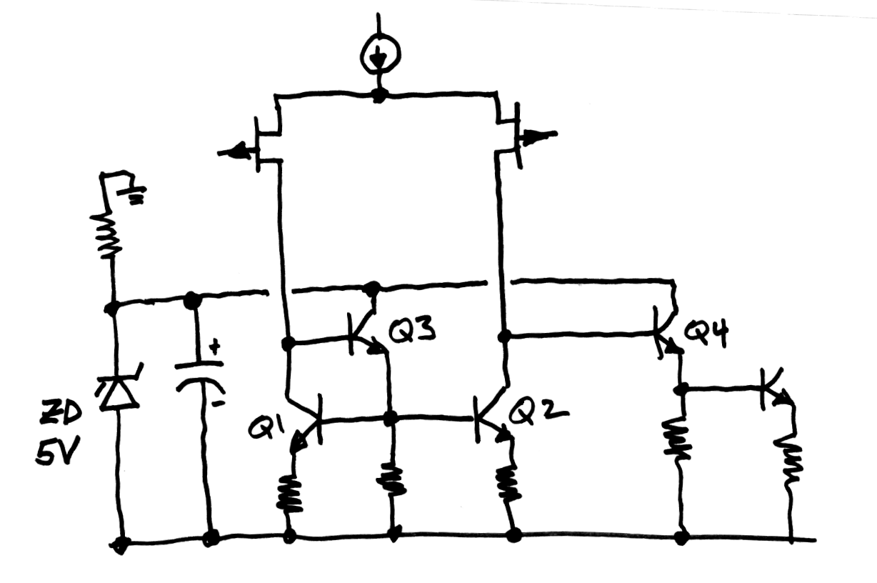
Spend the money to buy 3 extra parts (drawn at left) and get improved PSRR for your trouble. All four transistors Q1-Q4 are the same device type: low voltage, high Beta, high fT, low capacitance parts.
So then it's one of the possible options I mentioned earlier. An extra separate biasing network from the cascode, but shared by the helpers from both the mirror and vas.
Easy enough. Thanks.
Maniacs will use Nchannel MOSFETs in positions Q3 and Q4 since this increases LF gain still further. The 2N7002DW dual device matches pretty well in practice, even though there's no datasheet guarantees on matching. Buy ten duals (total cost: $2.16), test them all, select the one with best matching.
Maniacs will use Nchannel MOSFETs in positions Q3 and Q4 since this increases LF gain still further. The 2N7002DW dual device matches pretty well in practice, even though there's no datasheet guarantees on matching. Buy ten duals (total cost: $2.16), test them all, select the one with best matching.
Well, I'm not among the fet lovers' crowd, I don't like fets in the signal's path, just my preference.
Are you aware of the biasing problem with a comp diff pair with mirrors?
The fact that the bias point isn't well determined? If that, yes. But never had troubles in sims with that.
However I'm exploring some cascoding possibilities.
The fact that the bias point isn't well determined? If that, yes. But never had troubles in sims with that.
It may work in sims but it will NOT work in real hardware, many people have tried.
Bob C. adds some resistors to get around it.
It may work in sims but it will NOT work in real hardware, many people have tried.
Bob C. adds some resistors to get around it.
I haven't seen anything extra and different from what I've been doing, either in Bob's or Self's books.
What res are you referring to? That I need to know.
Spend the money to buy 3 extra parts (drawn at left) and get improved PSRR for your trouble. All four transistors Q1-Q4 are the same device type: low voltage, high Beta, high fT, low capacitance parts.
_
I agree.
Furthermore, in some cases, depending on the type of tail current source arrangement used, a relatively low-voltage reference that is with respect to the rail is needed anyway. One should not be foolish to save a couple of parts, and be careful when sharing voltage nodes among numerous functions. Make sure bypassing is good, that enough voltage node current is available, and that fault situations are handled gracefully. In some cases, for example, the VAS helper transistor can draw a lot of current in clipping or in a stuck rail situation, since the VAS transistor will be in saturation.
With respect to quasi-saturation it is important to keep it in mind, although with the IPS current mirror transistors running at only 1-2 mA in the helpered mirror it is not usually much of a problem. It is more of an issue for the VAS transistor. Having said that, if one uses low-voltage transistors with good quasi-sat performance in the current mirror, there is no need to use the same low-voltage transistor for the helper. It is easy to find good helper transistors with voltage ratings of 100V or more.
As I pointed out in my book, using a helpered current mirror with a 2T VAS is a good thing because now the two transistors in the current mirror are operating at about the same Vce, which also mitigates any quasi-saturation that does exist. The ordinary current mirror, with Vce only 1 Vbe, is far worse in regard to quasi-sat than the helpered one. That extra Vbe in the helpered version can make a very big difference with respect to quasi sat.
If you play your cards right with respect to emitter degeneration voltage drop in the mirror and the VAS, and systematic Vbe differences between the mirror transistors and the VAS transistors, the helpered arrangement allows the operating voltage difference between the collectors of the current mirror to be very small. That, in turn, allows the use of diode clamps across those collectors, which can improve overall behavior in clipping, including some reduction in sticking. That also can reduce the peak current in the VAS helper transistor under clipping conditions. This approach was illustrated in the DH220C amplifier I presented at Burning Amp last November.
Cheers,
Bob
R1 in the .pdf posted here:
http://www.diyaudio.com/forums/solid-state/31131-hafler-dh-200-220-mods-134.html#post4932974
http://www.diyaudio.com/forums/solid-state/31131-hafler-dh-200-220-mods-134.html#post4932974
- Home
- Amplifiers
- Solid State
- Current Mirror Discussion