Hi, havent done a proper test. I'm not going to be home until the weekend I might have time to run a test then.
But listening to it, output is getting close to 2volts. One of key design objectives for all sources is to standardise output to 2 volts. Will update in a few days.
Sent from my SM-G900I using Tapatalk
But listening to it, output is getting close to 2volts. One of key design objectives for all sources is to standardise output to 2 volts. Will update in a few days.
Sent from my SM-G900I using Tapatalk
Optical cartridge? Am I missing something? What is an optical cartridge? I have MM, MI, LOMC, HOMC and strain gauge cartridges. But no optical cartridges. Do you have any links?Thanks for the reply Hazard.
I am thinking of using a variation of the circuit for use with an optical cartridge which happens to be the cartridge of choice for me . The equalization should be pretty similar since the optical cartridge is also an amplitude sensing device.
Sent from my SM-G900I using Tapatalk
Hazard,
DS Audio
review
https://daviddenyerpr.co.uk/2016/07...udios-ds-w1-optical-cartridge-for-hi-fi-plus/
It is based on the Toshiba optical cartridge from about 30 years ago but using led's rather than a lamp.
Jam
DS Audio
review
https://daviddenyerpr.co.uk/2016/07...udios-ds-w1-optical-cartridge-for-hi-fi-plus/
It is based on the Toshiba optical cartridge from about 30 years ago but using led's rather than a lamp.
Jam
Thanks for the link, Jam. I've never come across one of these before but it does sound interesting (and out of my price range unfortunately). Are you using the DSAudio cartridge or do you have something different? One downside if the DSAudio would appear to be that you cant get the cartridge by itself, the preamp comes bundled with it. Soundsmith has the same problem. The local dealer won't, or maybe can't, sell a stand alone cartridge. He doesn't believe me that I can build my own preamp.Hazard,
DS Audio
review
https://daviddenyerpr.co.uk/2016/07...udios-ds-w1-optical-cartridge-for-hi-fi-plus/
It is based on the Toshiba optical cartridge from about 30 years ago but using led's rather than a lamp.
Jam
I assume that these cartridges need a power source for LED. A strain gauge is typically 750 ohm to 1k, and at a standard current of 4ma the drop 4v across the cartridge. But these would only drop the LED voltage? Say 1.7V?
Sent from my SM-G900I using Tapatalk
Hi Jam, sorry for delayed response. I've been playing around with moving coil cartridges lately, and the strain gauge is currently on the bench. But that's the best place to measure output, I had a quiet day at home today and had time to connect a signal generator to the strain gauge circuit and test output. And the answer is:Hazard,
What gain are you getting with the posted (latest) schematic unloaded?
Input (1k) = 10mV
Output = 4.68V
Gain = 468
This is pretty close to perfect for my system ( a happy outcome based on luck, not on any careful design
") ). As stated before I aim to get a standardised 2V from all sources, that way I don't need a pre-amp (I used to use passive attenuators, at the moment I am using a TVC). Strain gauge output is normally around 3 to 5 mV so gain is just about ideal. My DIY DAC puts out 1.55v for 0dB signal so these 2 sources match nicely. I haven't measured the gain on my moving coil stage, but with my Monster cartridge (0.24mV output) I am getting plenty of gain, the TVC is set to similar levels for all sources so that's a good outcome.
). As stated before I aim to get a standardised 2V from all sources, that way I don't need a pre-amp (I used to use passive attenuators, at the moment I am using a TVC). Strain gauge output is normally around 3 to 5 mV so gain is just about ideal. My DIY DAC puts out 1.55v for 0dB signal so these 2 sources match nicely. I haven't measured the gain on my moving coil stage, but with my Monster cartridge (0.24mV output) I am getting plenty of gain, the TVC is set to similar levels for all sources so that's a good outcome.Hi Hazard,
Thanks.......That is a fair amount of gain (53dB) if I am correct. For the optical cartridge 28dB is about what you need but that is easily adjustable. Do you buffer the diff. pair to drive lower impedances?
Cheers,
Jam
Yes, 53dB of gain. If transconductance of CFP is very high, then gain approximately equals Rload/Remitter = 2400/5 = 480.
I measured gain of 1,800 before degeneration applied so Gm can be considered to be high but not infinite so measured result of 465 matches theory quite well.
If you want gain of 28dB (say G = 30 in round figures) then you have 2 options:
1. Increase degeneration resistors R emitter = 2400/30 = 40ohm
2. Put a resistor across the drains to load down the output. A resistor of 300ohm should do it by my calculation (hint - don't trust my calculation!!).
3. Increase the tail current (say 20mA), decrease Rload (say 1.2k). Then the common mode resistor will be approx. 350ohm. Actually this is probably a good change to make, as it decreases output resistance.
I don't buffer the output of the diff pair. I couple the output through a Lundahl transformer (600 ohm 1;1). That seems to drive my power amps just fine without any pre-amp or buffer. Power amps have an input impedance of 1 meg. Gain control is provided by a variable resistor across the drains, and high output impedance has never been a problem. That said, a lower output impedance makes sense, I should increase tail current and lower the Rload (and degeneration resistors).
I did say - Don't trust my calculations.Yes, 53dB of gain. If transconductance of CFP is very high, then gain approximately equals Rload/Remitter = 2400/5 = 480.
I measured gain of 1,800 before degeneration applied so Gm can be considered to be high but not infinite so measured result of 465 matches theory quite well.
If you want gain of 28dB (say G = 30 in round figures) then you have 2 options:
1. Increase degeneration resistors R emitter = 2400/30 = 40ohm
2. Put a resistor across the drains to load down the output. A resistor of 300ohm should do it by my calculation (hint - don't trust my calculation!!).
3. Increase the tail current (say 20mA), decrease Rload (say 1.2k). Then the common mode resistor will be approx. 350ohm. Actually this is probably a good change to make, as it decreases output resistance.
I don't buffer the output of the diff pair. I couple the output through a Lundahl transformer (600 ohm 1;1). That seems to drive my power amps just fine without any pre-amp or buffer. Power amps have an input impedance of 1 meg. Gain control is provided by a variable resistor across the drains, and high output impedance has never been a problem. That said, a lower output impedance makes sense, I should increase tail current and lower the Rload (and degeneration resistors).
2400/30 = 40?? Sheesh.
Sent from my SM-G900I using Tapatalk
Hi
Have been planning to build your original design (post #1) ever since seeing it over on Vinyl Engine. It was more appealing than Flavio's opamp design because it had a lot in common with the fet-based opamps inside my active crossover.
You commented at the time that the gain was just enough for your Win, so for my Panny SG, I was going to reluctantly add SU transformers, so it's cool that the new version has increased gain. But I bought BL Toshibas at the time so am wondering if they're ok to use instead of GR's, or are there some value changes needed.
Appreciate you sharing your efforts for others who also want to max the performance of their quirky but amazing strain gauge cartridges.
Hi, don't know if you are still following this thread - I have bought a Technics/Panasonic EPC460, for fun. The new, improved circuit has plenty enough gain for this cartridge so if you haven't built it yet, you can proceed with confidence.
However, I prefer the WIN strain gauge to the Panasonic.
Regards, Paul
Hi Hazard..
As I mentioned in the Phobos thread, I have a new found interest in SG phono as a result of my visit to SoundSmith, and your writings. I too have purchased an EPC460 'for fun' and plan to build out a preamp, based on your design, using a Phobos PCB.
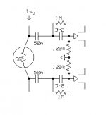
But as you point out, the SG response does not match RIAA after the 318us (500Hz) turnover. For what it's worth, here is a circuit, easily applied to your design, that corrects this, and includes the 50Hz rolloff. This mod will surely change the way it sounds. Will it be better, more accurate? I of course have no idea. I hope you try it out.
The math: the series value of the caps times the // value of the resistors = ~318us
As I mentioned in the Phobos thread, I have a new found interest in SG phono as a result of my visit to SoundSmith, and your writings. I too have purchased an EPC460 'for fun' and plan to build out a preamp, based on your design, using a Phobos PCB.
But as you point out, the SG response does not match RIAA after the 318us (500Hz) turnover. For what it's worth, here is a circuit, easily applied to your design, that corrects this, and includes the 50Hz rolloff. This mod will surely change the way it sounds. Will it be better, more accurate? I of course have no idea. I hope you try it out.
The math: the series value of the caps times the // value of the resistors = ~318us
Attachments
Hey Hazard, I have an epc451 and I would like to build your new circuit. Do you think you would improve it using the above eq network? Also, I am not exactly sure how you go about trimming the 10ma target you want? Is that just a j112 and a varistor to ground in the schematic? Or is it going to -12v?
Hazard the schematic for the new circuit is drawn using 3.18nF but you say 3.18uF in the text? Likewise the new schema says BC550 but you mention BC560 pnp in the text? Polyphase would your circuit require any changes given the new schema may not be accurate? Thanks very interested in building this.
Hey Hazard, I have an epc451 and I would like to build your new circuit. Do you think you would improve it using the above eq network? Also, I am not exactly sure how you go about trimming the 10ma target you want? Is that just a j112 and a varistor to ground in the schematic? Or is it going to -12v?
I bought myself a Decca Gold a few months ago and haven't been playing with Panasonic for a while now. So - I haven't tried Thomas' input eq network. Now I have built Thomas MC circuit and he knows his stuff so I'm sure that this circuit will perform well, but my suggestion is to try playing without any eq and see how it sounds. Most people use strain gauge without eq, my WIN does not need eq and a few of friends use Panasonic cartridges without eq. But the Panasonic I bought definitely needs a boost, in my system. So I don't believe that there is a hard and fast rule. There is a standard eq curve for magnetic cartridges, unfortunately there is no standard for strain gauges.Hazard the schematic for the new circuit is drawn using 3.18nF but you say 3.18uF in the text? Likewise the new schema says BC550 but you mention BC560 pnp in the text? Polyphase would your circuit require any changes given the new schema may not be accurate? Thanks very interested in building this.
Other stuff:
The input cap is 3.18nF. Together with 1meg gate resistor, this forms the 50Hz time constant.And the BJT is obviously pnp so its a BC560 (I did say in a previous post that you shouldn't trust my calculations. Don't trust my scematics, either). My current source is a cascode J111/J112, the current is set by a resistor between J111 source and -12V, and the J112 cascodes the J111. But there are so many ways to build a current source, you can do whatever you like.
As suggested in an earlier post by Jam, my strain gauge circuit may have too much gain. I have found this to be true and I have changed a few values to reduce gain, and this works well with WIN cartridge. But a Panasonic needs a bit more gain. I will see if I have time to draw an updated schematic.
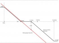
Back in Post #7 (April 2012!!) I was ruminating on eq requirements for a strain gauge, and suggested that a perfect displacement device would need a hf boost of 12dB to track the RIAA curve. I have re-attached the graph I exhibited back then. I didn't get much response, and as the WIN cartridge quite demonstrably had enough treble without any eq, I let the matter drop.
http://www.diyaudio.com/forums/analogue-source/211081-strain-gauge-jfet-pre-amp.html#post2992786
My interest was re-kindled when I bought a Panasonic EPC460 last year. I plugged this into my strain gauge pre-amp, and it was noticeably dull compared to the WIN cartridge. I recorded an LP through my 24 bit 192k sound card, I then opened the file in Sound Forge and experimented with eq. I got the best result with a treble boost of 4dB. Member Thomas posted a schematic in Post #33 which can be used to achieve this boost (more accurately, it is a shelf circuit that attenuates the bass).
Member Jam has now given me some more information, that has led me to this site
Audio Investigations: Equalizing the strain gauge
By coincidence this web page was written in April 2012, the same month I posted my initial thread! What a shame it has taken me so long to find this as Charkes Paterson has already covered the same ground, and reached very similar conclusion. Here are a few key quotes:
"The critical region requiring equalization is 500Hz to 2122Hz, right in the middle of the midrange. In this region, the treble must be shelved up at 6dB per octave to be the same as a velocity sensitive cartridge with no EQ. Since this region is just over 2 octaves, the total amount of equalization should be about 12dB. "
"But other strain gauge promoters who were not so hung up on ordinary audio engineering practices started producing high end strain gauge cartridge systems without using ANY electronic equlization. They did in fact have cartridges that needed less equalization than perfect strain gauge cartridges would because they already had a slightly rising frequency response characteristic. One of these Strain Gauge promoters was Sao Win, and his preamplifiers used NO equalization (and sounded mostly OK)."
"It turns out that even the Panasonic cartridges are not exactly perfect either. Just like the Win, they have a slight (but very slight) rising frequency response above 500Hz. They still need equalization for truly flat (correct) frequency response, but less than the 12.6dB that would nominally be required for a perfect position sensitive device."
"I thought it was about 10dB so I tried that. It sounded OK, maybe a bit thin. Counting on two octaves of equalization, I then tried 12dB of EQ. That was horrible. Rolling the EQ down to 6dB gave a nice warm bassy sound."
So experimentally I cam up with a requirement for 4dB boost for a Pana strain gauge, Charles decided on 6dB. Maybe I need less treble boost because my ribbon tweeters go all the way up to 11! But we are definitely in the same ball park.
So the corollary of this is -
1. If you have a WIN cartridge - there is no need for treble boost (not that I have already corrected for the 50Hz pole in my input circuit).
2. If you have a Pana strain gauge, you will probably need some treble boost 4 to 6dB. Thomas' circuit is a good starting point.
3. If you have some other displacement type device - you will need to figure it out yourself.
Thanks to Thomas and Jam for their inputs on this topic.
Attachments
Hi Paul,
The main reason I like the optical so much is you don't have a problem with inconsistency and having to to deal with a rising or diminishing high end besides it tracks much better than a strain gauge. All that is is requires is a simple correction and a low pass filter.
I used a Win for years and it was great apart from stylus failures and sample variation. Properly done very few moving coils can compete.
The optical can be a bit cost prohibitive now but hopefully that will change soon.
I suppose a circuit board is in order, so any volunteers?
Last edited:
- Status
- This old topic is closed. If you want to reopen this topic, contact a moderator using the "Report Post" button.
- Home
- Source & Line
- Analogue Source
- Strain Gauge jFET Pre-amp