Attached...
What Legendre said..
Also...
To check for basic wiring mistakes, I take a clean copy of the schematic and mark every connection with a highlighter as I find it in the amp.
Doublechecking pin numbers and connections on the tubes has caught a few mistakes, also.
Wiring around the inputs and volume pots would be one place I'd look.
Chassis ground connections would be another.
The output transformer secondary is connected to ground?
I might break out the volume pot and re-solder since I do have a spare. The input and output wiring are done pretty well. I believe I've got a good ground buss that runs throughout and everything is on there tight. The output transformer secondaries are grounded as well. Ugh
5965 tube - it can be wired 6.3v OR 12.6v heaters, correct? Do you have it wired up for 12.6v with a 6.3v heater supply?
I did that with 12AX7's on my very first scratch build when I was a noob, same symptom.
6.3 volts DC so... 4 > 9 and 5 > 9, right? Seems to be per schematic. I just looked but maybe I need to look with a fresh set of eyes.
5965 tube - it can be wired 6.3v OR 12.6v heaters, correct? Do you have it wired up for 12.6v with a 6.3v heater supply?
I did that with 12AX7's on my very first scratch build when I was a noob, same symptom.
The one I could see in the pic, looks to be wired correctly for 6.3 with pins 4,5 connected to one side of the heater supply and 9 to the other.
Attachments

The 5965 has a u = 47.
The Cathode spitter with a pseudo current source and resistive plate loads has a gain somewhat less than 1/2 of u (estimate about 20).
The triode wired 6V6 has a u = about 9
The 10k p-p transformer (1/2 winding is 2.5k/side) has a voltage loss to an 8 Ohm tap of 18.
(20 x 9)/18 = gain about 10 (20dB).
The iPhone has perhaps 1 volt peak out?
Try using a line powered CD player as the signal source (almost 3V peak at full scale). Use a Pop music CD or Country music CD, not a low volume classical CD.
Is there enough volume now?
If there is almost nothing coming out (not even hum) then boosting the input signal is not going to make the difference between non-working and working. The awful wiring layout means two things:
1. it probably contains mistakes
2. these will be hard to find
One possibility is that the whole thing (or a part of it) is oscillating at some inaudible frequency and this is blocking normal amplification. Or the OPTs have shorted turns - but unlikely to affect both channels unless the amp was briefly run with no output load early on and so managed to kill both OPTs.
If there is almost nothing coming out (not even hum) then boosting the input signal is not going to make the difference between non-working and working. The awful wiring layout means two things:
1. it probably contains mistakes
2. these will be hard to find
One possibility is that the whole thing (or a part of it) is oscillating at some inaudible frequency and this is blocking normal amplification. Or the OPTs have shorted turns - but unlikely to affect both channels unless the amp was briefly run with no output load early on and so managed to kill both OPTs.
Output transformers? That's a possibility-I could have done this. After replacing bias pots and volume pot (had spares and I didn't want to wonder), I managed to get more volume by using an old CD player as a source. One channel is quiet, but perfectly audible and sounds great. The other is super-quiet. Still no hum or hiss.
I feel the source of the problem(s) is narrowing.
Trying to get a scope this week; I need to bone up on testing in the mean time. For now I'm still testing the same portions of each channel voltages, resistance etc. Will also look up how to test output transformers. I ordered two more hammond 125d's since there will be another one after this regardless.
No one told me how much I didn't know ... I really have learned a lot in the last few weeks.
I ordered two more hammond 125d's since there will be another one after this regardless.
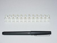
If you are stocking your parts bins, get a bunch of these:
https://www.surplussales.com/ELECTRICAL/TERMINALSTRIPS/TermStrip-6.html
They are absolutely an essential for me when building tube projects.
Attachments
If you are stocking your parts bins, get a bunch of these:
https://www.surplussales.com/ELECTRICAL/TERMINALSTRIPS/TermStrip-6.html
They are absolutely an essential for me when building tube projects.
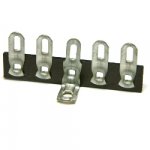
An excellent suggestion. And while you're at it, keep an eye out for this type of mounting hardware:

This is 'turret board', in a generic form which may be broken / cut to size and used as necessary. Turret board tends to be pricey, so any time you see some (like, inside of a junk chassis) try to salvage it. The stuff is worth its weight, when you want to make a pro build but printed circuits aren't available or even recommended for the application.
Time has taught us that tube gear can go the distance, decade after decade. If you want a build that is 100% solid and yet easy to maintain, turret board is a great way to go, along side of the various chassis-mount terminal strips and so on.
They can be quite convenient and workmanlike if they are anchored to the chassis- I see a lot of build pics where they are 'floating in space', which I won't do.I use European terminal blocks... easy to use, cuts to size, easy to make changes, check voltage and trouble shoot...and no soldering...
Do you connect components this way (resistors and caps) or just wires?
And, are you using solid or stranded wire?
BTW, for younger (?) readers, the ARRL Radio Amateurs Handbook usually had an excellent section on construction techniques. For tube gear, an older (1950s?) volume will be more useful. Check your public library or online used book source.
Victoria Guy,
I agree.
The ARRL Radio Amateurs Handbook is a great reference.
Every noob on this site should own one.
They are available online from the ARRL.
Support a good cause, purchase one.
(no I am not a "Ham")
At a 'Ham' swap meet, I purchased several from the 50s and early 60s for my technical workers, and gave them to them.
It is a great way to learn about electronics. The the theory sections will tell you about 95% of what you need to know about the fundamentals.
Last time I looked a few years ago, they still were good on the theory section.
Of course, the vacuum tube info is pretty much gone in the later year versions.
They can be quite convenient and workmanlike if they are anchored to the chassis- I see a lot of build pics where they are 'floating in space', which I won't do.
Do you connect components this way (resistors and caps) or just wires?
And, are you using solid or stranded wire?
I use wooden chassis, and attach them to the wood with screws. I would never recommend floating them. I use them for wires and components. I also use solid wire. In fact, I am currently using magnet wire as hook up wire. It's hard to find wire rated over 600v that's not aluminum or stranded. Also, the enamel makes for a good dielectric for audio signals...better than vinyl IMHO.
I am a firm believer in solid wire... keeps things in place. I like solid speaker wire too.
Be mindful when using aluminum wire with terminal blocks. Electrical current passing through aluminum against steel starts a corrosion process. So it's best to stay with copper and steel.
Last edited:
I use them for wires and components. I also use solid wire. In fact, I am currently using magnet wire as hook up wire. It's hard to find wire rated over 600v that's not aluminum or stranded. Also, the enamel makes for a good dielectric for audio signals...better than vinyl IMHO.
I am a firm believer in solid wire... keeps things in place. I like solid speaker wire too.
There's +absolutely nothing+ wrong with solid wires, and in fact, there's no good reason to use stranded in locations where flexing isn't an issue.
Solid-core wire has slightly better current specs than stranded of the same gauge, and doesn't have the handling issues (fragility) of stranded wires - particularly, the finely stranded wire often sold to audiophile types.
And it's great for speaker wires, too. And at those low voltages, the enamel / shellac insulation is a non-issue so far as handling & safety.
For audio, almost any insulation is fine provided it can handle the voltage and the heat - and even this does not matter if the wire is stiff and not touching anything.
Best to use a colour scheme to aid fault-finding. This probably requires PVC insulation - which is fine.
Best to use a colour scheme to aid fault-finding. This probably requires PVC insulation - which is fine.
Well I do have progress to report! The bad news is that I think we blew an output transformer. I obtained a oscilloscope, but I'm waiting on leads so I can do some more advanced testing.
My big problem is that I grounded one of the secondaries on the OT, and didn't match the primary impedance. One channel is still quiet. If that isn't it, it'll be a simple wiring issue in the audio circuit I haven't found yet, but will be revealed.
But the good channel ... holy smokes! Let's just say it doesn't disappoint. It really exceeds expectations. It's playing on old garage sale radio shack speakers in a huge garage and I couldn't stop listening to it.
I hear what everyone is saying about wiring. Once I the project got going I noticed I hadn't set aside real estate for power (we used small PCBs). So upside down we started expanding outward. With neatness out the window we just started to focus on getting it to work. It'll be partially disassembled and maybe put in another chassis ... who knows I think that's secondary to the main point that I wasn't sure we could pull it all off.
I'm sure now!
You guys rock so I'll check in.
My big problem is that I grounded one of the secondaries on the OT, and didn't match the primary impedance. One channel is still quiet. If that isn't it, it'll be a simple wiring issue in the audio circuit I haven't found yet, but will be revealed.
I don't understand this completely.
Do you mean you 'shorted' one of the secondaries on the OT? One end of the secondary OT winding should be connected to the ground for the circuit, as shown in the schematic, so 'grounding' one end wouldn't be a problem.
What troubleshooting (or inspection) steps have led you to the conclusion that you have a bad OT?
Also,I don't know what you mean about 'not matching the primary impedance' . Can you explain?
Yeah weird and I don't understand 100 percent myself. I'm using Hammond 125Ds. The data sheet says The OT secondaries go right to the speakers using 2 of 6 lugs to match the appropriate primary impedance. The schematic is for a different OT that says it has a black wire going to ground... (the Hammond doesn't have this).
So I wired the Hammond right to the speakers and got a better result.
I don't know for sure that the other OT is bad, but I'm waiting for my oscilloscope leads and I can't find any errors on that channel...yet. I suspect I might have ran it without a load or shorted it. I have found some troubleshooting data to check resistances across the primaries as a quick diagnostic. They both have the same values so maybe it is good.
I attached the Hammond data sheet.
Attachments
- Status
- This old topic is closed. If you want to reopen this topic, contact a moderator using the "Report Post" button.
- Home
- Amplifiers
- Tubes / Valves
- low output