Andrew, I remember that you have the same amp, Am I right?
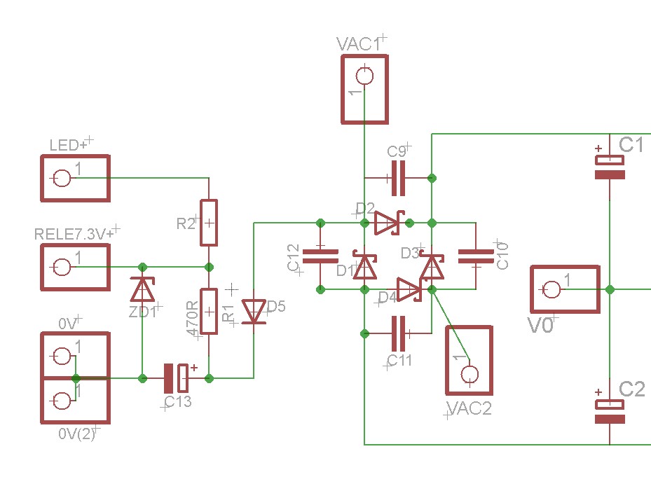
Here the Aaron No3 Millennium PSU toplogogy. Look the parallel C9...C12 at the diodes.

And here the Mark's preamp example. Look the parallel C14...C17 at the diodes.

That's why I am wondering about the Cs...If I am right I think that are same at the two examples. Mark says at the datasheet. that the C14..C17 can be evaluate as the Cx (except I am wrong with my bad English)
The high speed ripple seen in 1072 post removed with the increasing Cx from 0.01 to 0.1uF and Cs from 0.1-0.15uF to 1uF (post 1073).
Here the Aaron No3 Millennium PSU toplogogy. Look the parallel C9...C12 at the diodes.
And here the Mark's preamp example. Look the parallel C14...C17 at the diodes.
That's why I am wondering about the Cs...If I am right I think that are same at the two examples. Mark says at the datasheet. that the C14..C17 can be evaluate as the Cx (except I am wrong with my bad English)
The high speed ripple seen in 1072 post removed with the increasing Cx from 0.01 to 0.1uF and Cs from 0.1-0.15uF to 1uF (post 1073).
The capacitors across the rectifier diodes indeed do function as the Cx capacitors: in every half-period one of them is connected in parallel to the respective secondary.Andrew, I remember that you have the same amp, Am I right?
Here the Aaron No3 Millennium PSU toplogogy. Look the parallel C9...C12 at the diodes.
And here the Mark's preamp example. Look the parallel C14...C17 at the diodes.
That's why I am wondering about the Cs...If I am right I think that are same at the two examples. Mark says at the datasheet. that the C14..C17 can be evaluate as the Cx (except I am wrong with my bad English)
The high speed ripple seen in 1072 post removed with the increasing Cx from 0.01 to 0.1uF and Cs from 0.1-0.15uF to 1uF (post 1073).
However, in the case of a transformer built into a power supply (PS), the snubber resistance can also be determined in operation, i.e. when the PS is feeding a load. Connect the RS-Cs combination (the Rs being a trimmer) across the secondary, connect the scope, switch the PSU on, and taking the usual precautions (there are lethal volatges in a running PS!), adjust for a snubbed waveform at the falling edge, i.e. when a rectifier diode switches off.
My routine is to determine the Rs value using Quasimodo, and then to check the waveform at the secondary once again in a running PSU (with load!). In most cases, I get the correct snubbing with a value of Rs higher (less dissipation) than the one determined with Quasiomodo.
You might like to consult post #735, where I attached osillograms illustrating the procedure.
Regards,
Braca
Lemon, if you were making the effort to insert a snubber, then you may want to consider removing the original diodes and their parallel caps, and replacing with just UF4007 diodes (assuming original diodes are 1A type). The caps across the diodes can exacerbate noise, and usually indicate the need for better fast recovery diodes.
Last edited:
Yes, but I don't use it. It's back in it's box looking pristine.Andrew, I remember that you have the same amp, Am I right?
That's not the way I interpret the instructions.Here the Aaron No3 Millennium PSU toplogogy. Look the parallel C9...C12 at the diodes.
View attachment 587528
And here the Mark's preamp example. Look the parallel C14...C17 at the diodes.
View attachment 587529
That's why I am wondering about the Cs...If I am right I think that are same at the two examples. Mark says at the datasheet. that the C14..C17 can be evaluate as the Cx (except I am wrong with my bad English)
The high speed ripple seen in 1072 post removed with the increasing Cx from 0.01 to 0.1uF and Cs from 0.1-0.15uF to 1uF (post 1073).
The Cx & snubber are to be installed across the transformer windings.
Last edited:
For the transformer that is floating quasimodo gave 9r, for the one on the ps gave 24r and 11r with 2nd secondary shorted.
So guess I was wrong to think I can use the value quasimodo calculated without doing the short on the 2nd secondary.
Hi guys,
Sorry for the confusion created. I will explain myself a little better.
The 9r value came out when testing the dual secondary transformer with the primary and one of the secondaries shorted, quasimodo being connected one the other secondary.This transformer was floating, connected to nothing else than quasimodo.
The 11r and 24r values came from the transformer that is connected on the ps board tested under the conditions mentioned above.
Both transformers were same model(same va, v, a).
The resistor value that quasimodo calculates to be optimum for a floating transformer can get a zeta<1 with the transformer conneted to a bridge rectifier.
At this point how is better to tune the crc network?
With the transformer floating or connected in the circuit(bridge rectifier and smoothing caps) ?
The resistor value that quasimodo calculates to be optimum for a floating transformer can get a zeta<1 with the transformer conneted to a bridge rectifier.
It's the other way around - lower snubber resistance means more dissipation, means more damping, means higher Zeta values.
As I mentioned above, in a loaded PSU, the required snubber resistance tends to be higher than in the test bench measurement.
Just for the fun of it, you can have a look at the snubbing action in a running PSU and compare the waveform obtained with the one from the Quasimodo test.
Regards,
Braca
Circuit designers and DIY builders with a strong background in linear systems theory, are encouraged to play with the differential equations at different values of Zeta. You may find a value of Zeta that you like much more than the recommendation I make for beginners, the large-safety-guardband "Zeta=1.00". If you do, and if you are barraged with requests for tutoring and other technical support, I suggest memorizing this response: If you know what you're doing, you don't need my advice. If you don't know what you're doing, I advise you to use Zeta=1.00. If you're in between, re-read your textbook on linear systems theory.
...That's not the way I interpret the instructions.
The Cx & snubber are to be installed across the transformer windings.
Andrew, I have underlined some of your worlds.
There is some confusing about this. Across the secondaries is when the secondaries aren't center tapped! At the center tapped secondaries the snubber is across of windings but with contact to 0V with the same materials and values at the two halfs. Like that:

Before this, Mark says: "...when refurbishing or modifying existing audio equipment, it is quite likely that Cx is already fitted in the circuit. For example ... in D. Self's Elektor Preamp-2012, Cx=C14-C17=47nF."
From what I see, this topology is a Center Tapped Secondary. But the C14-17 is across the transformer windings but without contact to 0V!

And Mark says that C14...C17 is the same like Cx.
Is that the same topology like center tapped secondary?
I don't know I have confused...
Mark any suggestion, please!
Have I the same topology like Preamp-2012 or not. Are mine C9...C12 (100nF each) the same with Cx and don't need to add two Cx more?
No, as filters are not needed in this case.Are you using any filters in front of your scope when testing for correct rs and the ps is connected to the mains?
Just set the correct vertical sensitivity on the scope and connect the probe across the secondary.
Regards,
Braca
Damping ratio
Dan.
Oscillation cases
Where the spring–mass system is completely lossless, the mass would oscillate indefinitely, with each bounce of equal height to the last. This hypothetical case is called undamped.
If the system contained high losses, for example if the spring–mass experiment were conducted in a viscous fluid, the mass could slowly return to its rest position without ever overshooting. This case is called overdamped.
Commonly, the mass tends to overshoot its starting position, and then return, overshooting again. With each overshoot, some energy in the system is dissipated, and the oscillations die towards zero. This case is called underdamped.
Between the overdamped and underdamped cases, there exists a certain level of damping at which the system will just fail to overshoot and will not make a single oscillation. This case is called critical damping.
The key difference between critical damping and overdamping is that, in critical damping, the system returns to equilibrium in the minimum amount of time.
Dan.
Last edited:
C14 is in series with C8. So it is effectively across the power transformer.
Snubbing a schottky diode with a high value of capacitance is probably not a good idea. A capacitance of more then 500pF probably lets in more noise from the power line than it squelches.
Overall this is not a state of the art power supply design.
Better results would occur using a transformer snubber on each winding. Then using a full wave rectifier on each winding before filtering and regulation. The common or ground can best be combined after all of this. Another added technique is to reverse the phasing on the two transformer windings feeding the pair of bridge rectifiers and then adding a rail to rail capacitor to the outputs.
Hi,
I'm interested in building a Quasimodo; does anyone have a PCB available to sell me?
Thanks
I have a few pare spare Quasimodo V4 boards. You can have one at postage cost to you (I live in France) + any PayPal fees.
Here is a Quasimodo bom from Mouser.
This is a "through hole" BOM - right ?.
- Home
- Amplifiers
- Power Supplies
- Simple, no-math transformer snubber using Quasimodo test-jig