My first post.
I have a small guitar amplifier. I think the power transformer is not working. I am NO expert.
The voltage to the input of the transformer is 115AC. I checked that with meter. There is no output voltage. The output wires (3) show continuity. The input 2 wires show no continuity, infinite resistance. I think that means there is an open in the primary. I am not good at schematics. So,,, I have attached a schematic that may reveal to you what I need for a replacement transformer. The original has a label that does not show voltages. The numbers on the label are: MK-C0804023 and 070-010AG-30.
My question is what to buy and where. Can anyone help ?
Thanks.
Dave
Attachments
An open circuit primary probably means your transformer is scrap.
there was a Thread recently discussing this and a Member said the thermal fuse could be on the outside of the winding. So all is not lost yet.
Let him join in and guide you.
Or find the posts and PM him to get his attention.
there was a Thread recently discussing this and a Member said the thermal fuse could be on the outside of the winding. So all is not lost yet.
Let him join in and guide you.
Or find the posts and PM him to get his attention.
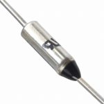
It sounds like a thermal fuse (that will be embedded in the windings) has failed. It is possible there is a fault that caused this such as a failed TDA2050 or a failed bridge rectifier.
The transformer is shown as producing -/+20 volts DC after rectification and so working back from this we get 20/1.414 (1.414 is root2) giving 14 volts AC.
It is quite possible the actual transformer is a 12-0-12 device. I say that because the voltage off load or at light loading will be higher than the rated value.
The other specification is to know its current rating. Measuring its size and weight is good for comparing transformers. I would guess somewhere in the region of 40 to 50va.
At one time Alliedelec.com was price winner on triad e-frame transformers. My usual supplier newark.com is high.
For example twin 14v winding at 2 amp per winding is <$19 + freight
Triad Magnetics - VPL28-2000 - leads 14V@4.0A 28V@2.0A sec: 56VA pri: 115/230V split bobbin Transformer - Allied Electronics
If the transformer is toroid, antekinc.com is popular among diyaudio users.
For example twin 14v winding at 2 amp per winding is <$19 + freight
Triad Magnetics - VPL28-2000 - leads 14V@4.0A 28V@2.0A sec: 56VA pri: 115/230V split bobbin Transformer - Allied Electronics
If the transformer is toroid, antekinc.com is popular among diyaudio users.
It is possible there is a fault that caused this such as a failed TDA2050 or a failed bridge rectifier.
Have you done any checks to make sure there isn't an obvious short anywhere (that would have caused the transformer to fail) ?
Although you can only do a basic resistance check it is worth confirming the rectifier/s are OK and that there isn't a very low resistance measurable across either rail and between rails which could point to a failed TDA output chip.
And just to add a safety note to all this...
The thermal fuse is a front line safety device which means that fitting an off the shelf replacement transformer (that almost certainly doesn't have such a fuse) is altering the designed in protection. Something you should be aware of.
I would suggest when its all fixed and running that you add (if one isn't there already) a small in-line fuse of suitable rating for the transformer chosen.
(and just reading from the beginning, we are not 100% sure it has such a thermal fuse anyway, it could just be a failed primary... it happens)
Mooly,
Thanks for your concern. I have done no checks. I would if I knew how, I am such a novice that I could not recognize the items to check. A little background : I got this amp free, it was going to be trashed. I have some other amps, so the need for this is not urgent. I figured the cost of this repair was worth the gamble. It sure would be smart to check that stuff before applying the voltage but I would need to be trained first. Thanks again.
Dave
Well a couple of pointers.
In your PDF the bridge rectifier is the four diodes D11,12,13 and 14. You should check that none reads short circuit.
IC11, the TDA2050 can be tested for shorts by connecting your meter across pins 3 and 5 which if you look is the same as reading across from rail to rail.
A really good tip for initial testing is to use a dbt (dim bulb tester) which is a mains filament household bulb of 60 to 100 watt rating (60 would be ideal for this) and which you connect in series with the mains feed.
If there is a fault then the bulb will light as excess current is drawn. If there is no fault then the bulb filament stays cold (and cold = low resistance) and so the amp would power up normally.
News :
The new tr arrived. Preparing to install, I removed old one. Deciding that it was probably scrap, I carefully peeled back the first layer of blue plastic wrap just to ensure the primary input wires were actually attached to the fine wire inside and found the thermal fuse embedded below the surface. Checked continuity, none. Jumped the fuse, got continuity through primary, applied 115v, checked output, found 16 vac, reassembled, and powered on. This amp now looks and works like brand new. Operated it for about 15 minutes, no problems or noticeable heat. Thanks to all who offered advise and suggestions. Now to decide whether or not to replace thermal. There is a fuse in the input 115v line.
The new tr arrived. Preparing to install, I removed old one. Deciding that it was probably scrap, I carefully peeled back the first layer of blue plastic wrap just to ensure the primary input wires were actually attached to the fine wire inside and found the thermal fuse embedded below the surface. Checked continuity, none. Jumped the fuse, got continuity through primary, applied 115v, checked output, found 16 vac, reassembled, and powered on. This amp now looks and works like brand new. Operated it for about 15 minutes, no problems or noticeable heat. Thanks to all who offered advise and suggestions. Now to decide whether or not to replace thermal. There is a fuse in the input 115v line.
in many japanese amps that i serviced those small traffos, there is always a
thermal fuse built in, sometimes it is just a matter of choosing the
right pins to bypass the fuse, at other times the fuse is in between windings..
you were lucky this time...
just use the correct size mains fuse on you power inlet and you can re-use that traffo...
thermal fuse built in, sometimes it is just a matter of choosing the
right pins to bypass the fuse, at other times the fuse is in between windings..
you were lucky this time...
just use the correct size mains fuse on you power inlet and you can re-use that traffo...
I have to prompt you into asking this question:News :
The new tr arrived. Preparing to install, I removed old one. Deciding that it was probably scrap, I carefully peeled back the first layer of blue plastic wrap just to ensure the primary input wires were actually attached to the fine wire inside and found the thermal fuse embedded below the surface. Checked continuity, none. Jumped the fuse, got continuity through primary, applied 115v, checked output, found 16 vac, reassembled, and powered on. This amp now looks and works like brand new. Operated it for about 15 minutes, no problems or noticeable heat. Thanks to all who offered advise and suggestions. Now to decide whether or not to replace thermal. There is a fuse in the input 115v line.
What made the Thermal Fuse open?
Was it a moment of abuse? Unlikely.
Was it prolonged abuse? very likely.
What kind of prolonged abuse could have been imposed such that the Thermal Fuse opened?
Great to hear the amp is working 
Andrew... you would be surprised how common thermal fuse failure is in a service environment. They often do fail for no apparent reason even in equipment with a constant current draw and no user influence (such as abusing an amp etc). They are a pain.
The safety question that arises though is as to what course of action you take. If I shorted the thermal fuse out in your clock radio that was in for repair and then at some later date a 'real' fault occurred overloading the transformer (say a shorted rectifier) and the radio melted or started smoking (or worse), who would be liable.
The thermal fuse is a front line safety feature.
The thermal fuse is a front line safety feature.
it truly is, and you see the same fuses fitted to electric fans, they fail as open circuit,
one time only, non resettable...
so when these devices sensed dangerously high coil temps that can lead to fires,
they do their job of interrupting the circuit to prevent further damage...
in a power traffo, overvolting the primary leads to saturation and high currents
that leads to high temps, these devices ensures fires will not result from this...
Attachments
- Status
- This old topic is closed. If you want to reopen this topic, contact a moderator using the "Report Post" button.
- Home
- Amplifiers
- Power Supplies
- small power transformer