Jfet measurement jig
I am currently matching my jfets using a breadboard. But I wanted to make something more permanent.
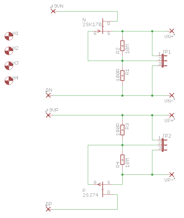
The nicest arrangement I found was the one from runoffgroove. It allows idss and Vp measurement.
A closer look at the Fetzer Valve
The 10M used for Vp still allows some current through the jfet, but it should be close enough for matching.
Here is my schematic
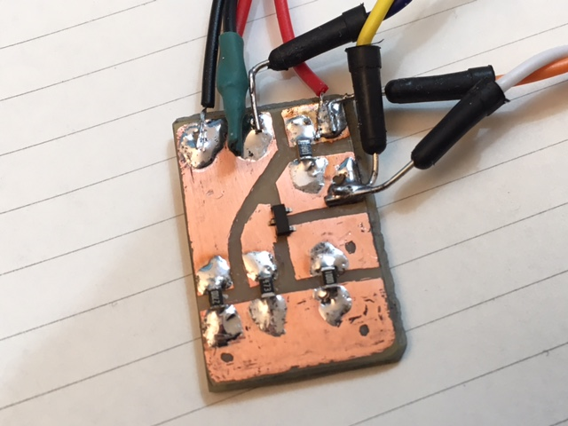
And this is the pcb
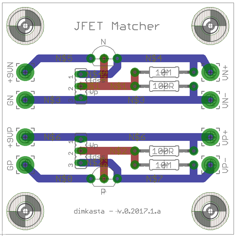
A jumper or a switch will be used to change between idss and Vp mode.
I will order the pcb on Monday. In the meantime any input is welcome.
I am currently matching my jfets using a breadboard. But I wanted to make something more permanent.
The nicest arrangement I found was the one from runoffgroove. It allows idss and Vp measurement.
A closer look at the Fetzer Valve
The 10M used for Vp still allows some current through the jfet, but it should be close enough for matching.
Here is my schematic
And this is the pcb
A jumper or a switch will be used to change between idss and Vp mode.
I will order the pcb on Monday. In the meantime any input is welcome.
Attachments
Last edited:
Better allow for surface mount devices -- TO-92's are going the way of the dodo.
Yeah I was already working on that
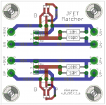
")
It allows for any drain/source pinout combination, so that non-symmetrical devices can be measured.
D marks the drain.
Through hole devices can just be reversed if they have a different pinout.
Attachments
I bought some of these SOT23-6 test sockets. Turns out that the SOT-23-3 package (which encloses diyAudio's favorite JFET, the BF862) is merely a subset of the SOT-23-6 package. So you can buy a socket for the latter and use it to measure the former.
Although if the ultimate goal is matching, as implied by the title of this discussion thread, shouldn't the test jig have sockets for TWO Nchannel JFETs and TWO Pchannel JFETs? Shouldn't the test jig measure delta-Vpinchoff and delta-Idss ?
Although if the ultimate goal is matching, as implied by the title of this discussion thread, shouldn't the test jig have sockets for TWO Nchannel JFETs and TWO Pchannel JFETs? Shouldn't the test jig measure delta-Vpinchoff and delta-Idss ?
Thanks for the suggestions guys.
Mark yeah you are right.
I changed the title to avoid any frustration from people reading the thread.
We could add a second circuit for each jfet sex and add an opamp subtractor at the output to get the delta.
But I am not sure how useful it would be given the extra complexity. Both in circuitry and methodology. Not to mention the extra identical DMMs that would be required.
It is pretty straightforward to run through a stash of jfets marking them one by one, and then matching them by value.
The delta is still easily apparent by the values.
Trying to match unknown value jfets by delta will be more tedious since we will have to go through all combinations. And if we still want to measure and mark each jfet at the same time to ensure appropriate operation levels and to avoid meaningless and redundant trials, we are back at square one, only now we need three identically calibrated DMMs for each jfet sex.
Not worth it in my opinion
I bought some of these SOT23-6 test sockets. Turns out that the SOT-23-3 package (which encloses diyAudio's favorite JFET, the BF862) is merely a subset of the SOT-23-6 package. So you can buy a socket for the latter and use it to measure the former.
Although if the ultimate goal is matching, as implied by the title of this discussion thread, shouldn't the test jig have sockets for TWO Nchannel JFETs and TWO Pchannel JFETs? Shouldn't the test jig measure delta-Vpinchoff and delta-Idss ?
Sort and bin, then match. So not side by side delta matching.
Erno's test jig:
Here's the original article:
http://www.audioxpress.com/assets/upload/files/Erno BorbelyJFETs The New Frontier Part 1and 2.pdf
Since we cannot control the final application's temperature, then we can just hope that the devices will drift closely enough.
This means that if we keep them from heating up, we can test them during a period of time with a relatively stable temperature. We just have to use a largish heatsink to keep them cool enough to more or less room temperature for the entire measuring session. Something like a chunk of aluminum drilled for TO92.
If you worry about matching different batches tested on different occasions that can wildly vary, then just keep the measured batches separate, and make sure that you verify the match with a fresh measurement when you pick them up for your application
And if you want to be super obsessive about it, build your application with a random pair just so that it works, and then run the test jig inside the chassis to verify the measurements on real operating conditions.
This may be an argument in favor of testing pairs of JFETs and measuring the deltas. You know the two devices were tested at the same time under the same temperature conditions (and if thru-hole, you can join them thermally using rubber bands). By clever application of precision diffamps and/or precision current mirrors, you can measure the delta with a single meter (rather than subtracting the readings of two different meters that might not be identical).In my personal experience the problem with these measurements is to keep the condition constants. If you are looking for a precision matching at +- 0.1 mA you have to find a way to control the temperature of the devices.
You can also perform a first pass, coarse "bin assignment" using one-at-a-time measurements, and then on the second pass, if bin number X contains N parts, pairwise test each of the (N x (N-1)/2) possible pairings.
Too much work imo for something that will be tested in the actual circuit anyway.
If I wanted to get more spot on without access to the final application (for example if we are selling matched pairs), then I would build a stripped down version of DCB1 and B1 R2 with sockets and measure the DC on the output.
For this I see more value in adding some curve point measurements
If I wanted to get more spot on without access to the final application (for example if we are selling matched pairs), then I would build a stripped down version of DCB1 and B1 R2 with sockets and measure the DC on the output.
For this I see more value in adding some curve point measurements
I have gone through this pair matching of To92 transistors.Thanks for the suggestions guys.
Mark yeah you are right.
I changed the title to avoid any frustration from people reading the thread.
We could add a second circuit for each jfet sex and add an opamp subtractor at the output to get the delta.
But I am not sure how useful it would be given the extra complexity. Both in circuitry and methodology. Not to mention the extra identical DMMs that would be required.
It is pretty straightforward to run through a stash of jfets marking them one by one, and then matching them by value.
The delta is still easily apparent by the values.
Trying to match unknown value jfets by delta will be more tedious since we will have to go through all combinations. And if we still want to measure and mark each jfet at the same time to ensure appropriate operation levels and to avoid meaningless and redundant trials, we are back at square one, only now we need three identically calibrated DMMs for each jfet sex.
Not worth it in my opinion
It is easy and quick to measure Idss and/or Vpinchoff of a low to medium current jFET.
It takes at least ten times longer and probably closer to 50 times longer to pair match devices over a small range of operational currents.
But it is worth doing if the devices are going to operate at any Id that is lower than Idss.
The Pass B1 and Salas DCB1 operate the jFETs at 100% of Idss. Simple quick selection of Idss is sufficient for these two Buffers.
For an LTP input pair, the two will probably operate at anywhere from 10% to 90% of Idss and pair matching of the Id vs Vgs curve is in my opinion mandatory. That's what I sold in swap meet. It took me hundreds of hours to match up the 600 lsk170.
That was intended as a service to the UK Members here.
But they were half asleep, the majority went abroad and much of that was wasted feeding DCB1 which were all the rage at that time.
Last edited:
it's really quite easy to see how the differential current/voltage of a poorly matched pair works.This may be an argument in favor of testing pairs of JFETs and measuring the deltas. You know the two devices were tested at the same time under the same temperature conditions (and if thru-hole, you can join them thermally using rubber bands). By clever application of precision diffamps and/or precision current mirrors, you can measure the delta with a single meter (rather than subtracting the readings of two different meters that might not be identical).
You can also perform a first pass, coarse "bin assignment" using one-at-a-time measurements, and then on the second pass, if bin number X contains N parts, pairwise test each of the (N x (N-1)/2) possible pairings.
A single pair jig that holds the two flat face to flat face . Clamp them together.
Common the gates. Common the sources.
1k0 ±0.1% drain resistors to +10V, or a bit more.
Attach a variable gate to source voltage.
Measure the difference in drain voltage using a DMM.
adjust the gate/source voltage to sweep over a range of drain current.
Watch the DMM voltage go everywhere except reading zero ! and that could be for a previously selected very accurately matched Idss pair.
The variation in gm seems to vary almost as much as the Idss for jFETs.
Tj is probably the most difficult thing for us to keep constant.In my personal experience the problem with these measurements is to keep the condition constants. If you are looking for a precision matching at +- 0.1 mA you have to find a way to control the temperature of the devices.
I really could not find a good solution yet.
D.
We certainly can't know what Tj is with any precision.
What we can do with a comparison style measurement is control the case temperature and the power dissipation. Then there is a resonable chance that the Tj of the clamped devices to have similar Tj. But that test Tj will NOT be at the standard 25°C
this technique does nothing to address the variation in gm. That works against one whenever the devices are operated at a lower Id.Since we cannot control the final application's temperature, then we can just hope that the devices will drift closely enough.
This means that if we keep them from heating up, we can test them during a period of time with a relatively stable temperature. We just have to use a largish heatsink to keep them cool enough to more or less room temperature for the entire measuring session. Something like a chunk of aluminum drilled for TO92.
If you worry about matching different batches tested on different occasions that can wildly vary, then just keep the measured batches separate, and make sure that you verify the match with a fresh measurement when you pick them up for your application
And if you want to be super obsessive about it, build your application with a random pair just so that it works, and then run the test jig inside the chassis to verify the measurements on real operating conditions.
Selecting for Idss alone is a waste of time if you then operate them at some other current, sometimes as low as 10% of Idss.
- Status
- This old topic is closed. If you want to reopen this topic, contact a moderator using the "Report Post" button.
- Home
- Amplifiers
- Pass Labs
- Jfet matching jig