"i don't know if the PPSL is becoming directional at 300"
The depth of the plenum means it should be crossed at 250hz or so.
In the late 80's Electro-Voice marketed a PPSL that they crossed at 800hz to a pair of DH1 compression drivers. The response got a little bumpy from 300hz~800hz. With the DSP available today you could probably make it work OK.
http://r.search.yahoo.com/_ylt=A0LEVvtmknpY.akAqm0nnIlQ;_ylu=X3oDMTByOHZyb21tBGNvbG8DYmYxBHBvcwMxBHZ0aWQDBHNlYwNzcg--/RV=2/RE=1484456679/RO=10/RU=http%3a%2f%2fwww.electrovoice.com%2fdownloadfile.php%3fi%3d971684/RK=0/RS=lG5gBPDIWh_Bl_G.GNklGI2lAjE-
I think you can see why I suggest no more than 250hz, although the peaks and dips are no more than about ±3dB over the midrange.
A LR24 requires the woofer to be -6dB at the crossover point, so we should be OK with 250hz.
The 3FE25 will also be -6dB down at the crossover point with the LR24, they should like that.
I would play around with adding a touch of EQ and try a 300hz crossover if you like, it will probably work OK.
There is not a lot of added stress going from 300hz down to 250 hz in any event.
I may have to model your 24x line and see what it looks like.
Last edited:
Thanks djk
Am I right here
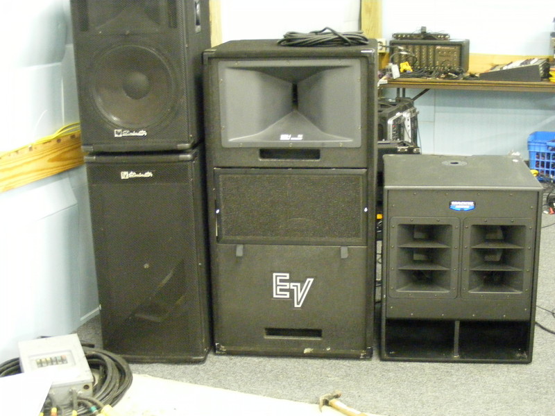
The bottom half of the EV is the PPSL section I need and should allow me to cross over at a -6db point around 250Hz. Similarly my tower should hopefully be at -6db at around the same freq. Do I adjust this to 'smooth out' the any peak/dip at the xover point, my brain tells me two speakers operating in the same region can amplify or attenuate depending on phase.
Thanks again
Am I right here
The bottom half of the EV is the PPSL section I need and should allow me to cross over at a -6db point around 250Hz. Similarly my tower should hopefully be at -6db at around the same freq. Do I adjust this to 'smooth out' the any peak/dip at the xover point, my brain tells me two speakers operating in the same region can amplify or attenuate depending on phase.
Thanks again
Last edited:
In summary
A line array and bass bin system capable of covering a 300 people venue but also usable as a vocal PA for smaller venues. Rack system to contain amps processors/crossover/controllers, EQ, power distribution etc.
Lets work with this.
Last time I did something like this, I mic'd everything and put it all through the PA. Here's what I used, which was enough for the situation. Anything smaller would likely have struggled.
2x 18" active subs
2x 2x10" tops
The subs weren't great (Mackie Thumps), but had plenty of 50Hz oomph. I couldn't get my subs to that gig, so used the band's. The tops are bi-amped with an NU6000DSP a side, 2x Faital 10FH520 and 1x 18Sound ND1460 on a 90x40 horn. You're looking at around 3KW when the clip lights come on (the 10"s are fine with that, though the HF unit wouldn't survive for long). Crossover was 100Hz.
Getting that performance from a line of 3" drivers will be difficult. The 10"s have approximately the same cone area as 10x 3" drivers, so you'll need 20 per side. That's if they have the same amount of excursion available as the 10"s. Those 10"s have 7mm one-way travel, so the 3"s will need the same. Alternatively, you can double the number of drivers (40 per side) and use 3.5mm one-way travel. That's at the upper-end of sensible for a 3" driver, but we can work with that. The problem now is that the line array has made its way through the ceiling and is annoying the people on the next floor.
You do gain some headroom in the 3"s by crossing over higher. 1 octave will gain you 12dB, so a 200Hz crossover might be better. 12dB gain there would mean you can use 10x 3" drivers per side. More sensible.
You could probably match the performance of those Mackie subs with a good ported 15", or maybe a very nice 12" in a 55Hz tapped horn. Whatever you choose, it's gonna need to be clean past 200Hz, though, to match the column.
I would recommend replacing the SM58s with something that'll reject sound from the sides. Super/hypercardiod. Reason is that a tall slim column has very little directivity control, and will be throwing a lot of sound on to the stage. Your mics need to reject that sound if feedback is a concern.
Chris
I ran a plot on the 3FE25.
With 24 in a box they would be x-max limited at 200hz on a sine wave with 480W RMS input.
In reality, this would not be an issue as the signal from the crossover would be 6dB down around 250hz or so.
It looks as if one PPSL with 1.2KW has enough output to keep up with a pair of tops, a pair might be overkill.
Hi Chris
Thanks for looking at this.
I'm gonna have to get a bigger van. From just googling the points you have raised here I have learned a lot.
Can you recommend any good books on the subject?
How did you arrive at the 3K figure and is this per side?
Are you just dialling down the top output on the crossover to control power to the ND ? (is the NU6000 channel feeding it turned up to max ?)
24 x 3" drivers compares well with 2 x 10" in your system for cone area but how you calculate the total excursion for multiple speakers in both cases?
I ran a plot on the 3FE25.
With 24 in a box they would be x-max limited at 200hz on a sine wave with 480W RMS input.
In reality, this would not be an issue as the signal from the crossover would be 6dB down around 250hz or so.
It looks as if one PPSL with 1.2KW has enough output to keep up with a pair of tops, a pair might be overkill.
djk
Thanks again for your help here.
I'll also ask you if you can recommend some good books on the subject
I'd be grateful if you could send me the modelling of the 24 array. It would help my understanding of the subject no end.
Also if you have any plan or drawing for a 15" PPSL it would be a great or is it good enough to go with the drawing here?:
High Efficiency Speaker Asylum
Thanks again
Hi Chris
Thanks for looking at this.
I'm gonna have to get a bigger van. From just googling the points you have raised here I have learned a lot.
Can you recommend any good books on the subject?
How did you arrive at the 3K figure and is this per side?
Are you just dialling down the top output on the crossover to control power to the ND ? (is the NU6000 channel feeding it turned up to max ?)
24 x 3" drivers compares well with 2 x 10" in your system for cone area but how you calculate the total excursion for multiple speakers in both cases?
Most of what I've learned have been learned through these forums or my own experience. Stick around.
")
The 3K figure is the amount of power the amps will be delivering if you drove up to clipping. The NU6000 will do 2KW/ch into 4ohm, 1.2KW/ch into 8ohm. The 10"s are 8ohm, wired in parallel to channel 1, so that's 2KW between them. The 8ohm HF is on the other channel, so will get about 1KW. The active crossover takes care of relative levels etc, though IIRC I've got 8dB of attenuation on the HF amplifier channel. I run the volume knobs wide open and control volume from my mixing desk. Those power figures are per side - I drop one NU6000DSP behind each speaker, run a short 4-core cable between the amp and speaker, and then send XLR and power.
Regarding excursion,
SPL is a function of frequency, cone area, and excursion. If you multiply cone excursion by cone area, you've got the volume of air the cone is moving. When you get to big subs, the Vd (Volume displaced) figure is important. Car audio and home theatre enthusiasts often compare their systems on this figure. Anyway, I tend not to do the maths there - I keep cone area and excursion seperate.
So lets say I'm comparing a 12" driver and an 18" driver. The 12" has pretty much exactly half the cone area as the 18". So, if you want to make the same noise with each, the 12" has to have twice the linear excursion of the 18". You could also use 2x 12" with the same excursion. If you go down an octave, you need 12dB more output. A double of excursion gives 6dB more output, so going down an octave needs 4x excursion (two doubles). Doubling cone area is like doubling cone excursion, +6dB.
So lets say you've got an 18" driver giving 90dB at 40Hz. A single 12" driver would have to move twice as much to give the same SPL. A single 12" driver at 80Hz would have to move half as much.
Piston Excursion calculator
In the example of the 10"s...
According to my sims, at 90v input the cone excursion on the 10"s reaches 9mm one-way at 110Hz. It's going to be a pretty serious 3" driver to match that, but, as we've seen earlier, you can take the crossover up and get some of that back.
Lets talk 1 for 1 for now, and then change the crossover frequency and see what's what.
We'll call it 100Hz to keep the numbers easy.
Our model 3" driver has 3mm one-way travel, and you need 12 of them to match the cone area of a single 10". So, to get the same volume displacement as 1x10", you need 36 of them (or, 12 of them running at 9mm excursion). I had 2x10" a side, so that's 72 of those Visaton units if you want to match the SPL of those 10"s at 100Hz.
If you take it up to 200Hz instead, you gain 12dB of SPL. That's the same as two doubles of cone area!
So, 1/4 of 72 is now 18x 3" drivers. That's more sensible. Playing around with the caliculator linked above will confirm this - 18x 3" drivers at 200Hz and 3mm excursion will match 2x10" drivers at 100Hz and 9mm excursion.
If you're happy to take a 6dB penalty on SPL, you can use 9x 3" drivers with a 200Hz crossover and get something pretty respectable.
All you need to do is ensure your drivers will reach the excursion required at the crossover frequency without burning up. You won't get them to hit Xmax at 1kHz, but 200Hz will probably be possible.
HTH
Chris
"Also if you have any plan or drawing for a 15" PPSL it would be a great or is it good enough to go with the drawing here?:"
The dual 15 PPSL plan and cut list for the Kappa Pro 15LF2 is what I refer people to. There is a brace down the middle of the port, across the back, and up the other side.
Shorted the ports to 15" for drivers like the JBL 2225/26
The 3FE25 model is not complete as it will not connect the drivers as needed, it is good enough the show box size, the -3dB point, x-max, and total output at full power.
I may build a pair of lines with 18 drivers each (36 drivers in a case), less than 1.5dB of maximum output is lost, and it will be an easy 4Ω load for the amplifier. F3~130hz, 1 cu ft, Qtc~.775, about 124dB output at 360W input.
djk
thanks again for your help
Trying to get to grips with all the different aspects of what needs to be known here. I need to separately understand all of the parameters involved here to appreciate your conclusions and not happy just to follow blindly. I will get there though. I wasn't expecting you to actually consider building the columns
Thanks for taking your time to look at this
what the model is not calculating is the improved loading of the drivers when supported by neighbouring drivers. it is known that in an array of subs the outer ones are experiencing excursion limiting. I'm currently considering building an ADAU1701 board with 8 ch amps (4 TPA3116's) for 3Fe32 or 4FE35's , to build a steerable array. just built a dual_ch dsp board with 2 TPA3123's for a 2way system.nanoDSPAMP ..
not shure where this project would fit : PA, line level or amps
not shure where this project would fit : PA, line level or amps
what the model is not calculating is the improved loading of the drivers when supported by neighbouring drivers. it is known that in an array of subs the outer ones are experiencing excursion limiting. I'm currently considering building an ADAU1701 board with 8 ch amps (4 TPA3116's) for 3Fe32 or 4FE35's , to build a steerable array. just built a dual_ch dsp board with 2 TPA3123's for a 2way system.nanoDSPAMP ..
not shure where this project would fit : PA, line level or amps
Thanks for looking in
I'm a lot more familiar with Arduino and Atmel than Audio and I recently wrote a sketch to control my pedal board. Any combination of 8 pedals, plus data out to midi pedal (Line6 M13) and display to show song name and current pedal config. Just call up song from memory and use inc/dec footswitch to change pedal config. Saves needing 4 feet.
. Will build when I get time.I appreciate the coupling effect of elements of the array but don't fully understand it yet.. I'm currently getting to grips with WinISD and maybe you can help. When you initially setup a vented box in WinISD do you have to add the port volume separately to the enclosure or does the initial volume for the box include the vent volume too?
Your DSP looks interesting but too much for my needs here I'd say. I'll have a good look at
it soon. Looks like a great deal of control available using multiple amps/dsp. Could this be used in smaller venues (2-300 people) successfully?
wakko.
I'm a pure HW guy, allergic to ";". the DSP solution is intrinsically cheap an ADAU1701 costs 4euros in china, a TPA3116 75 cents for 2CH amp. curently planning a horizontal line array to restrict the sound to a terrace. my wife recently started a bar.
re WinISD you will have to add the driver volume and port volume to the airvolume used to calculate things to get the total box volume.
re coupling, this holds true only for LF. the effect of stacking subs is always more than 3dB as they start to radiate better when the air of neighbouring subs is pushed forward by the neighbour.
basreflex,
From what I can see the lines are blurring between DSPs and Microcontrollers these days. DSPs are way more advanced for audio use but they also have GPIOs which can be programmed. Can I ask you how you would use these ADAs to implement the system you spoke of. Sounds like a very cost effective and modular setup. Do you build the control boards and mount in the ADA ICs ? What way do you use the dsps to control signals to the amplifiers.
From what I can see the lines are blurring between DSPs and Microcontrollers these days. DSPs are way more advanced for audio use but they also have GPIOs which can be programmed. Can I ask you how you would use these ADAs to implement the system you spoke of. Sounds like a very cost effective and modular setup. Do you build the control boards and mount in the ADA ICs ? What way do you use the dsps to control signals to the amplifiers.
the easiest way for me to "talk" to the dsp is using an analog voltage from a potentiometer. to read from the dsp (overload and signal present indicators for example) the GPIO is used with a fet transistor buffer to drive a LED. I used a DAC post filter amp with a mute control and undervoltage lockout. the undervoltage lockout is triggered when the voltage before the regulator is too low. the mute is driven by a timer in the DSP. Upon startup of the DSP the GPIO lines are softly pulled high as the reset mode, and you have to make sure the mute is then also active.
I once ran short of GPIO's as I used all the I2S signals, and I have used the analog dac output as GP out as timer driven mute signal. you can find a host of examples on the ezanalog board.
I once ran short of GPIO's as I used all the I2S signals, and I have used the analog dac output as GP out as timer driven mute signal. you can find a host of examples on the ezanalog board.
- Status
- This old topic is closed. If you want to reopen this topic, contact a moderator using the "Report Post" button.
- Home
- Live Sound
- PA Systems
- Bose L1 type PA build