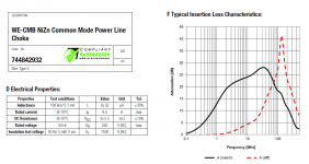
The extracts from the datasheets below show 3 excellent Nanocrystalline CM chokes with very low DCRs that I may be able to use in signal input to reduce the common mode noise coming from my BD player with a SMPS power supply.
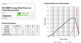
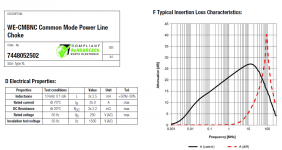
These 3 CM chokes have inductance values of 32uH, 1mH and 2.5mH respectively. But their "Typical Insertion Loss Characteristics" are much closer than their respective inductances indicate.
It makes me think if the inductive values are relevant. I mean, if you create LCR filters based on the inductive values, the response will be much different from those in the "Insertion Loss Characteristics".
How can I design the LCR filters based on the datasheets? How can I know the inductance values for sure, because if the values are not accurate, the LCR filter can create more noise than it needs to reduce. Obviously, if 32uH could do what is in the graph, it will be far easier to implement because the damping resistor need not be high, whereas with 2.5mH the damping resistor may be so high that the RC filter (even with L=0) can roll off the 20kHz signal!
Please help me to understand how to read the datasheets for CMCs.
Attachments
Those are suited to power line applications, not signal. Also because their DCRs are so low the attenuation they're giving isn't particularly high. For a BD player I'd have thought a 0.5A current rating would be plenty, then even normal ferrite CM chokes will give CM inductances in the tens of mH.
Did you notice that the insertion loss was given at different frequencies? Insertion loss, of course, also depends on the details of what comes after. This is unstated, but may be some industry standard for a mains supply.HiFiNutNut said:These 3 CM chokes have inductance values of 32uH, 1mH and 2.5mH respectively. But their "Typical Insertion Loss Characteristics" are much closer than their respective inductances indicate.
Thanks, guys. It makes sense. I have not found any descriptions from the manufacture on how the insertion loss was measured. But maybe 50 ohm system was used.
Abraxalito,
It is not used for the BD player internal. It is used in the preamp to clean up the CM noise coming from the BD player as I found as long as the interconnect is connected to the BD player a lot of ground noise is shown in the entire audio chain from my scope.
See the picture below. I tested using a 3.3mH CM choke at the input of my preamp and subjectively it cleaned up the sound quite a bit. I had to use some resistors in series as well as in parallel with the CM Choke on both the signal and ground sides so that possible resonances are damped. Without the damping resistors the sound was not as clean.
But going further seems to be difficult, because if I model the LCR circuits using the inductance given I found that it requires quite a high value of R to make the LCR damping effective, but higher R rolls of the signal below 20kHz. I could not buy a lot of those CM chokes for experiments because they are quite expensive.
Attachments
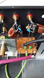
Very low DC resistance of the CM choke was chosen because I don't want to introduce impedance on the ground line. There is no series resistor on the ground line but the signal line only. Both windings of the CM choke need a parallel resistor for damping. A capacitor joins the 2 outputs of the CM choke.
If the series resistor value is too high, it rolls of the signal below 20kHz. If it is too low, the LCR forms some peak at around 100kHz that increases noise.
If the parallel resistor value is too high, it is ineffective in damping and there is peaking. If the parallel resistor value is too low, it shorts the coil at lower frequencies and makes the CM choke ineffective.
To find the optimal values, I need to know if the inductance values given by the datasheet is reliable to use.
Please help verify my thoughts on SMPS noise.
The SMPS of my BD player switches at 100kHz. But I think the CM noise is not at 100kHz, but probably from MHz to tens of MHz. This is because there are no sine waves at 100kHz, and the rise and fall time is much faster.
If this assumption is correct, then the CM choke inductance needs not be high - perhaps 500uH to 1mH is sufficient. Right or wrong?
How do you filter out CM noise in the signal line?
It is not used for the BD player internal. It is used in the preamp to clean up the CM noise coming from the BD player as I found as long as the interconnect is connected to the BD player a lot of ground noise is shown in the entire audio chain from my scope.
Yes I deduced from what you wrote that you were using these chokes on the audio connection between player and preamp. Your photo confirms this. However its not the configuration that these kinds of CM chokes are intended for. On audio interconnects the load impedance is typically 10k or higher and could be as high as 1M on some preamps, so trying to get an estimation of the insertion loss from the DSs is suspect because as davidsrsb points out those plots are normally made with 50ohm as the load impedance.
If you put the same choke in the power lead to the player then you should get the same or even better cleaning of the sound. You'll not need the damping resistors with it in the mains lead - most likely you need those because your load impedance is so high. Note that you'll only need a single choke in this configuration so why not put two in series?See the picture below. I tested using a 3.3mH CM choke at the input of my preamp and subjectively it cleaned up the sound quite a bit. I had to use some resistors in series as well as in parallel with the CM Choke on both the signal and ground sides so that possible resonances are damped. Without the damping resistors the sound was not as clean.
As regards your assumptions about the frequency of the CM noise, 100kHz would be the frequency with the highest amplitude so the choke does need to be chosen to attenuate that frequency.
Last edited:
2 CM Chokes in series have been planned. Yes, I have been wondering how they can work with high load impedance. When modelling them as pure inductors I guess I could only achieve about 6dB attenuation with LTSpice but my ears may be saying there is more. I could not get attenuation down to 100kHz. 1MHz, yes.
If you don't think these are the right chokes for the job, any tips on what you think should work? I use them because they have the lowest DCR which is necessary for the application. Any smaller chokes will have higher DCR. We don't want to introduce resistance in the ground line.
I have installed a full Mains Filter box for each player. Yes it cleans up the sound quite a bit. But the CMC in the signal input also does a job.
The load impedance thing is more complex than I sketched out in my post because the graphs are for the CM insertion loss but the preamp's load impedance will be DM (differential mode).
I think they'll work better in the mains lead because there the resistance is only a second-order issue. I agree that resistance in the signal screen is a bad thing. But you've two effectively in parallel (in regard to CM noise) so you're halving the inductance and hence the attenuation.
I think they'll work better in the mains lead because there the resistance is only a second-order issue. I agree that resistance in the signal screen is a bad thing. But you've two effectively in parallel (in regard to CM noise) so you're halving the inductance and hence the attenuation.
I would use ferrite beads on signal lines.
Both the flow and return pass through the bead and thus the ferrite does not experience any net current flow and thus no inductance. No audio signal is filtered.
But if there is a common mode interference signal on both or one signal line then the ferrite does see a net current flow and the inductance impedes that current flow . The subsequent capacitor to chassis filters off the interference. But only at the frequencies where the inductance is significant. Usually above the audio band.
You can apply ferrite beads to the SMPS outputs, but both the flow and return must pass through the bead. You can wrap an extra turn through the bead if your bore diameter can take four insulated cores. This will help attenuate common mode interference when there is a low impedance to chassis after the bead.
It is normal to install the bead just outside the chassis of the receiver and the grounding capacitor just inside the enclosure to minimise the interference that stays on the internal cabling.
Last edited:
The published inductance will hold good up to a bit below the point where the graph of attenuation stops going up and starts coming down.
Thanks. I thought so. It is good to have somebody who knows much better to confirm.
I would use ferrite beads on signal lines.
Both the flow and return pass through the bead and thus the ferrite does not experience any net current flow and thus no inductance. No audio signal is filtered.
But if there is a common mode interference signal on both or one signal line then the ferrite does see a net current flow and the inductance impedes that current flow . The subsequent capacitor to chassis filters off the interference. But only at the frequencies where the inductance is significant. Usually above the audio band.
You can apply ferrite beads to the SMPS outputs, but both the flow and return must pass through the bead. You can wrap an extra turn through the bead if your bore diameter can take four insulated cores. This will help attenuate common mode interference when there is a low impedance to chassis after the bead.
It is normal to install the bead just outside the chassis of the receiver and the grounding capacitor just inside the enclosure to minimise the interference that stays on the internal cabling.
I have tried both manufactured CMCs and my own winding of CMC on low frequency ferrite rings. They sound different, probably due to different implementations. Your suggestion reminds me to do more to complete my experiments.
When I used my own CMC wound from a ferrite ring with only 2 - 3 turns, I didn't use appropriate resistor damping. I think I will give it another try with appropriate RC network surrounding the ferrite because at certain frequencies the ferrite is an inductor. I didn't take that into consideration previously.
Without knowing which frequency range is relevant to your problem, I would guess nanocrystalline toroids are the best bet when it comes to wideband filtering common mode chokes.
Probably vacummschmelze vitroperm toroids are the most effective ones.
This may work between 100kHz and some 100MHz.
Ferrite beads are preferrable at higher frequencies starting at some 10MHz.
Probably vacummschmelze vitroperm toroids are the most effective ones.
This may work between 100kHz and some 100MHz.
Ferrite beads are preferrable at higher frequencies starting at some 10MHz.
Those clamp-on ferrites can be a real blessing or curse.
I once clamped a couple of them on the power cord of my Blu Ray player at the power entrance and got obvious distortions when hearing music!!! The only explanation is that it must have caused resonances in the power line so severe that the SMPS supply could not get rid of the noise.
But now on my power amps power supplies after rectification using some CLRC (with very small L and R), in the 3 wires (+, -, GND) between the 2 Cs, I clamped on 5 "clamp-on" ferrites and the sound become much cleaner! This is the cheapest and most obvious upgrade to my power amp I have ever made! If you have not done so, please try it and report back here!
I guess the ferrites with all 3 lines of +, -, GND running through them won't get saturated because the sum of the current is 0 with the additional CM noise being filtered out. I think I may try some resistors in parallel with them so that at lower frequencies where the ferrites act like inductors the resistors can provide necessary damping.
- Status
- This old topic is closed. If you want to reopen this topic, contact a moderator using the "Report Post" button.
- Home
- Design & Build
- Parts
- Common Mode Chokes - Inductance or Insertion Loss?