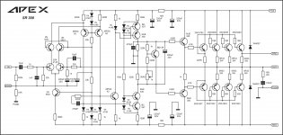
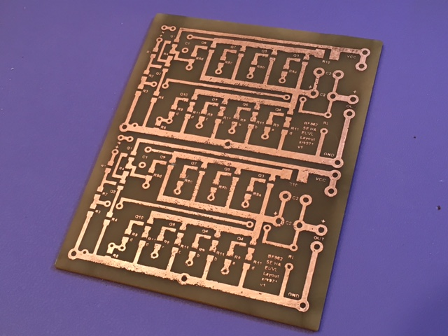
This, nice schematic, deserve a decent layout ,don't you think ?")
Yes, use this schematic.
Regards
Attachments
Hi Mile,
Have ever done a power amp in smt?
I see you are using a smt 2sk2145. Why not make it as much as possible using smt, like DMMT5551 and DMMT5401 duals, smt res and cap as much as can be done for the low power passives. Of course the higher power stuff (bjts) needs to be THT, but using as much smt will make the pcb much smaller. And of course smt really requires a 2-sided pcb min., as it would be impossible to do it 1-sided in smt. Also one would have to have CNC data(gerber and drill) to fab, but we all know we can get cheap 'out of China these days.
Just an idea to contemplate
Thanks
Rick
mr mile
I've Series a 100w bulb to Transformer primary
my audio sours is my com
my transformer is +-33v ac and about 5 ampre
my speaker is 4ohm
my amplis bias is about 19mv
when i turn on amplis the bulb turn on in volum 60 and up
and in volum 80 my amplis sound are distorted
is it normally??
if this isnt normal in your opinion which one has problem?my trafo or my amplis?
respectfully
The bulb test is used to prevent hazardous experiences (like short circuits, for instance).
Once you've turned on successfully at low power, you should disconnect the bulb.
If not sure to do that, place another 100W bulb in parallel, and so on.
As volume rises, so does the input current. Hence, the bulb will drop the AC mains voltage, what will make your amp sound harsh.
Once you've turned on successfully at low power, you should disconnect the bulb.
If not sure to do that, place another 100W bulb in parallel, and so on.
As volume rises, so does the input current. Hence, the bulb will drop the AC mains voltage, what will make your amp sound harsh.
Last edited:
Single side pcb with SMD parts can be DIY friendly... you can made pcb with SMD parts for any of my amp. I want diy friendly projects with TH parts in retro style.
I have been having some fun of late hand drawing my own SMT layouts with a Sharpie marker and making small head amps. I then moved to using iron on transfers and that works really well. You can make some tiny amps with this method and the parts are so cheap and good quality. I would be interested in making an SMT Apex amp - there are some pretty neat MOSFETs in SOT-23 that can pump some power too - and they are like $0.60 to $1.60 from Digikey (so genuine). What are some SMT alternatives for the venerable BC546/557/550/560/etc? And what are SMT alternatives for VAS and drivers KSC3503/KSA1831 or BD139/140? Or should one just stick with through holes on those items?
I would love to make a 50w Apex FH12 that fits in an Altoids mint tin
The heat is another issue though... Bc856c/857c/850c/860cI have been having some fun of late hand drawing my own SMT layouts with a Sharpie marker and making small head amps. I then moved to using iron on transfers and that works really well. You can make some tiny amps with this method and the parts are so cheap and good quality. I would be interested in making an SMT Apex amp - there are some pretty neat MOSFETs in SOT-23 that can pump some power too - and they are like $0.60 to $1.60 from Digikey (so genuine). What are some SMT alternatives for the venerable BC546/557/550/560/etc? And what are SMT alternatives for VAS and drivers KSC3503/KSA1831 or BD139/140? Or should one just stick with through holes on those items?
I would love to make a 50w Apex FH12 that fits in an Altoids mint tin
Start the amplifier with buib connected,no input signal!mr mile
I've Series a 100w bulb to Transformer primary
my audio sours is my com
my transformer is +-33v ac and about 5 ampre
my speaker is 4ohm
my amplis bias is about 19mv
when i turn on amplis the bulb turn on in volum 60 and up
and in volum 80 my amplis sound are distorted
is it normally??
if this isnt normal in your opinion which one has problem?my trafo or my amplis?
respectfully
View attachment 590298
You must see the bulb lighting for a short and then slow come to dark
Measure the output for d.c presence.You must measure something up to 80mV.
If this occur,turn off the amplifier ,disconnect the bulb and connect the amplifier direct to mains.
Put two resistors 10-20R instead of fuses. Turn on the amplifier. Measure the voltage on these resistors.If your measure is up to 3-4v ,turn off again leave for capacitors discharging. Put the fuses in place.Turn on and enjoy!
xrk971.
I suggest to give diptrace a try instead of your method.
Your method is what I used in college in the late 70's when people were still using donuts and tape.
With diptrace you can print out to pdf(bullzip)/laser and use the same fab process and also get a proper pcb done with pcbway.
Stick with KSC3503/KSA1831 or BD139/140, as the smt option is a sot-223, does not save any room and is harder to cool, since you only have pcb copper area to act as a HS.
Even our old fav's like ksa992/ksc1845 are available in sot-23, FJV992,1845. Toshiba has a few nice ones too, 2SA1312,2SC3324.
with smt, you can use really nice thin film R from Susumi and high voltage NPO/COG MLCC, which are of the highest quality. Of course the higher cap devices still need to be film and AlumElectrolytic. I can solder up a smt way faster than THT, which I find to be a PITA, since you have to lead form, hold in place, trim, what a waste of material. smt is green, THT is wasteful.
Good luck
Rick
Last edited:
Bc856c/857c/850c/860c
Thanks, Thimios - a new small world awaits me
xrk971.
I suggest to give diptrace a try instead of your method.
Your method is what I used in college in the late 70's when people were still using donuts and tape.
With diptrace you can print out to pdf(bullzip)/laser and use the same fab process and also get a proper pcb done with pcbway.
Stick with KSC3503/KSA1831 or BD139/140, as the smt option is a sot-223, does not save any room and is harder to cool, since you only have pcb copper area to act as a HS.
Even our old fav's like ksa992/ksc1845 are available in sot-23, FJV992,1845. Toshiba has a few nice ones too, 2SA1312,2SC3324.
with smt, you can use really nice thin film R from Sum and high voltage NPO/COG MLCC, which are of the highest quality. Of course the higher cap devices still need to be film and AlumElectrolytic. I can solder up a smt way faster than THT, which I find to be a PITA, since you have to lead form, hold in place, trim, what a waste of material. smt is green, THT is wasteful.
Good luck
Rick
Thanks, Rick. I totally agree that THT is wasteful and slower. I have a bucket with the collected snips from all my THT builds in the past year. How much lead would into a landfill had I thrown that 10lbs of clippings into the trash? It is slow to bend leads, solder, and snip I agree. The quality of the SMT parts is what is also attracting me to them. NP0 caps cost almost nothing.
I need to learn layout software "one of these days"
Someone told me once that one-of-these is not a recognized day of the week. I actually used PowerPoint to make my first SMT layout - and it works pretty well. OK for simple stuff.
Here is a 10 JFET SE Class A head amp made with PowerPoint and a laser printer:
thanks mr thimiosStart the amplifier with buib connected,no input signal!
You must see the bulb lighting for a short and then slow come to dark
Measure the output for d.c presence.You must measure something up to 80mV.
If this occur,turn off the amplifier ,disconnect the bulb and connect the amplifier direct to mains.
Put two resistors 10-20R instead of fuses. Turn on the amplifier. Measure the voltage on these resistors.If your measure is up to 3-4v ,turn off again leave for capacitors discharging. Put the fuses in place.Turn on and enjoy!
i know them
but i said why bulb is light in volume 60 and up
in your opinion my traffo is problem( for example is weak) or sound sours is very strong for my ampli???
why sound is distorted in volum 80 and up??
Start the amplifier with buib connected,no input signal!thanks mr thimios
i know them
but i said why bulb is light in volume 60 and up
in your opinion my traffo is problem( for example is weak) or sound sours is very strong for my ampli???
why sound is distorted in volum 80 and up??
What is the bulb condition without (no sound source) signal?
Start the amplifier with buib connected,no input signal!
What is the bulb condition without (no sound source) signal?
with no signal bulb is off
thanks mr thimios
i know them
but i said why bulb is light in volume 60 and up
in your opinion my traffo is problem( for example is weak) or sound sours is very strong for my ampli???
why sound is distorted in volum 80 and up??
This question has been answered!
(post http://www.diyaudio.com/forums/solid-state/173462-studio-reference-amplifier-239.html#post4941862)
This question has been answered!
(post http://www.diyaudio.com/forums/solid-state/173462-studio-reference-amplifier-239.html#post4941862)
thanks mr max
i had not seen ur answer!
sorry
Looks good xrk971.
As you probably already know, drawing up a pcb with no linkage(netlist) to a schematic is very error prone, difficult and time consuming. Take your time and learn, go through the tutorials to use diptrace, you would be surprised at what you can do when you put your mind to it.
If everyone contributes and helps each other by sharing designs and libraries, it makes life so much easier. I think that is the idea of DIY, to share knowledge and learn how to design electronics. Let the computer do some of the tedious hard work.
I find it surprising and puzzling, that this thread being now at #2400 and still not one design done using any ecad. It is like I am in a time warp back to my early electronics days. Come on guys lets try to progress into the modern age.
Last edited:
- Home
- Amplifiers
- Solid State
- Studio Reference Amplifier