Fluid,
Good points and thanks info, look forward next year how your First One M amp and new TC9 array turns out.
Regarding massive heat for better AB quality amps verse family of better quality digital amps future will tell, have preferred AB family myself but after listening BeoLab 90 speaker then quality of amps was not a thought and in they sit inside speaker systems DSP corrected AC pass band they maybe end up as good as AB amps.
The cabinet that I build will be much simpler than the two towers at least for the first try, but will definitely incorporate some of the tips and tricks that have been shown in this thread. I am looking forward to hearing what they sound like as there has been so much positive feedback in this thread.
I have an 8 channel UCD based amp as well, virtually no heat sink except the chassis panels. They sound excellent and very dynamic but there is something that good AB amplifiers do to the sound that is hard to describe but obvious when it is missing.
If you want a lot of power without the heatsink then the Ncore amps seem to be ideal. They are also designed with a differential input if that is important. I would really like to hear one to see if they can perform as well as a good AB design but the price is a bit steep for me.
I have to think that practically using a sub or two for the really low frequencies is probably a better solution than pushing the small drivers to xmax with a big amp.
When you have the sort of DSP ability to deal with frequency and phase issues that has been shown here it seems that integration should be doable.
When you are using an active crossover and only asking a driver to produce very low frequencies then the 'speed' of it seems a bit irrelevant. Being able to time align the fundamental from the sub and the transient from the array should get the best of both worlds?
I can agree to that, fluid, that was my line of thought as well. Though I have thought about the way the arrays load those low frequencies, basically spreading them out over a long vertical and thin horizontal area. It seems to work well to get an even response out in the room.
I am wondering how 2 subs would do in comparison. I'd use them together with the lines, by scaling down what I ask the lines to do.
Fun to read about your plans though, I hope you'll document that journey for us to follow.
I am wondering how 2 subs would do in comparison. I'd use them together with the lines, by scaling down what I ask the lines to do.
Fun to read about your plans though, I hope you'll document that journey for us to follow.
...All those little drivers hitting 17Hz are working together and provide a very quick reaction time.
A big 15" or 18" driver will sound sluggish and won't be able to keep up with the arrays.
I think his only option might be a line array, or two, for subs. Something like ten or twelve 6" drivers would be better suited to the task, but would probably have the lowest WAF possible...
...Open for debate is the fact that my moving mass is 65 gram currently. With the SD area of a 15/16" woofer. Would a sub (or 2 or 3) be sluggish? Even if it only has to do 20 to 40 HZ?...
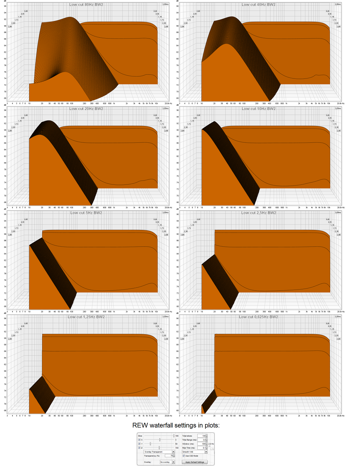
Debate then . . . . this talk about sluggish bass isn't just because of IRR domains lowest stop-band point and XO's behavior that the lower in frq point a XO executed and steeper in slope the worse is the delay, and that makes us think big area woofers is slow and never integrate speedy because they often XO'ed lower than small woofers and totally ruins step response and square waves having a little look alike DC component (horizontal X axis). Example is pro gear where ported bass boxes also often have lowest stop-band high passed to protect system and limit excursion and that high pass makes delay even worse. Ten or twelwe 6 inch woofers as Perceval talk about will not be any faster that it takes IRR filters to pass electric signal and if XO point is as low as 40Hz they get sluggish i think, with only exception if XO is FIR powered and inherent CPU release time for sound stream is accepted. Attach waterfall visual below of IRR audio pass-band domain behavior without a real IRR XO-point inside that pass-band area that think interesting to study, it shows clear that the lower in frq lowest stop-band perform the cleaner and probably faster perceived is first wave and delayed tail will move lower and lower away not muddy important mids. TC9 towers with 17Hz f3 would be between plot 3 and 4 and actual think have seen they perform close to that to die for 20dB clean ridge thru mids area.
...unless integrated into a wall with fabric to cover the drivers... Sorry BYRTT.")
Free world
in past myself was sold first time when got into a room with walnut enclosure and real original JBL 18 incher, but this threads TC9 arrays is in live situation as impressive looking....But BYRTT, your count is off, I do use 50 TC9's, not 48
Sorry had numbers wrong thanks important correction
Attachments
I recommend everybody to try the My-ref Fremen Edition amp for the towers.
Superior to the First One in my ears, but First One is among the very best.
I have tired First One - My_ref - Pass amps in many variations - amazing FET circlotron - Fetzilla - Roender's FC-100 - OTL 6c33 - Goldmund Telos clone among others..
Only problem with My_Ref is limited power out, but a bridged version would be more than enough. Haven't tried that yet.
I always pay attention when you post about these amps. As said, I don't have a lot of experience on that front yet, having had the Amp I use ever since I bought new in ~1990. It was quite the investment for me at that time buing that 20 Kg monster with dual power supply. I've taken good care of it though with regular scheduled maintenance. I still love that thing. So much that when I went shopping for an ambient amp I bought the less powerful middle of the road Pioneer amp from that same time period.
Thanks BYRTT,
This plot within REW has always made me wonder:
I'm always puzzled by it, how does it get/interpret that graph. To me, the APL plots make more sense (here centred at 23 ms).

Here's the APL measured plot of my DAC. that makes so much more sense to me visually than how REW presents it's graph. I can compare that to what my arrays are doing...

The REW plot always makes me wonder from which side I'm viewing the data. For it being a straight edge all the way down as in your lowest cut-off does not relate to the APL plot of my DAC. That one shows a gradual build up at bass frequencies on one side and the drop off on the other side.
This plot within REW has always made me wonder:
I'm always puzzled by it, how does it get/interpret that graph. To me, the APL plots make more sense (here centred at 23 ms).
Here's the APL measured plot of my DAC. that makes so much more sense to me visually than how REW presents it's graph. I can compare that to what my arrays are doing...
The REW plot always makes me wonder from which side I'm viewing the data. For it being a straight edge all the way down as in your lowest cut-off does not relate to the APL plot of my DAC. That one shows a gradual build up at bass frequencies on one side and the drop off on the other side.
I can agree to that, fluid, that was my line of thought as well. Though I have thought about the way the arrays load those low frequencies, basically spreading them out over a long vertical and thin horizontal area. It seems to work well to get an even response out in the room.
I am wondering how 2 subs would do in comparison. I'd use them together with the lines, by scaling down what I ask the lines to do.
Fun to read about your plans though, I hope you'll document that journey for us to follow.
Agreed.....and how I would approach adding subs would be 2nd order LP on the subs and only a first order on the arrays.....more of an overlap than a crossover in the conventional sense. Otherwise, typicall LF modes will return and muddle the response..............and THAT'S what people refer to as slow bass....is the modes and room interaction. To think that a large cone is slower than a small one in general due to size is quite ridiculous.
Those with big rooms, wallets and balls could take it another notch with Infinite baffle or Dipole subs with lots of EQ and power. Interesting combination the IB sub and thin full range array......the least obtrusive home theater application.
...The REW plot always makes me wonder from which side I'm viewing the data. For it being a straight edge all the way down as in your lowest cut-off does not relate to the APL plot of my DAC. That one shows a gradual build up at bass frequencies on one side and the drop off on the other side.
If I understand correct then expect your first APL_TDA plot is a perfect impulse DC to lightspeed probably created in Rephase, and second APL_TDA plot is a DAC loopback. If that is correct it makes sense because both sound card input and output have delay because of AC coupling capacitors and that delay is the ridge curve swinging to right side in low frq area, so what happens to right side of ridge is what we look at in REW waterfall but inverted, and with that i mean in REW low frq are at left side and high frq is at right side but if we go stand at right side in APL_TDA and face wall we will get low frq at right side and high frq at left side.
Does this sound right or have i something wrong about plots, will have to leave 1-2 hours and get back.
No, the first plot is a measured result of my DAC by routing it's output to my soundcard's line-in with APL_TDA.
The second APL plot is a measurement with mic in sweet spot of my arrays with APL_TDA. As can be seen with the little stuff being upset in my room on the right side of the graph.
What a fun welcome to wake up to, an exploding discussion touching a lot of interesting points... now where do I start to react to this.
Well, well! When I asked the innocent question about subwoofers for the arrays back in post #2799 I knew you wouldn't be responding immediately due to the time difference between us. What I didn't realize was the DIYaudio elves would make themselves busy overnight designing said subwoofer along with its amp, and rearranging/redecorating your listening room as well!

I noticed you jumped immediately to a sealed box arrangement for this future subwoofer and I was wondering why. You've clearly given it some detailed thought and I'm hoping to glean from your thought process.
Hi CraigSu,
Yes... an innocent question. I'd go for sealed subs for their better time response. A port would always be firing 180 degree out of phase. OB would be an option, but way bigger.
If I steal the picture from BYRTT which he took while visiting:
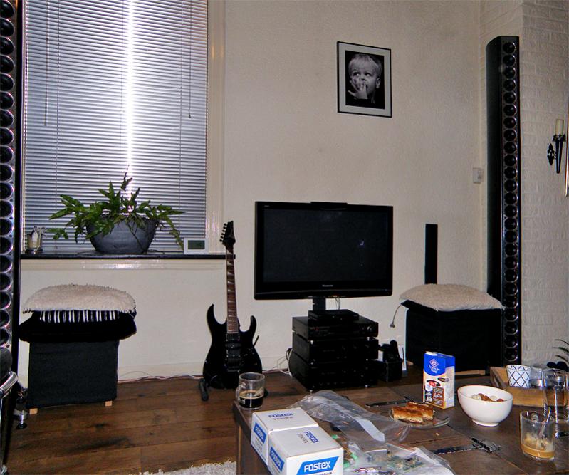
... or the one from xrk971:
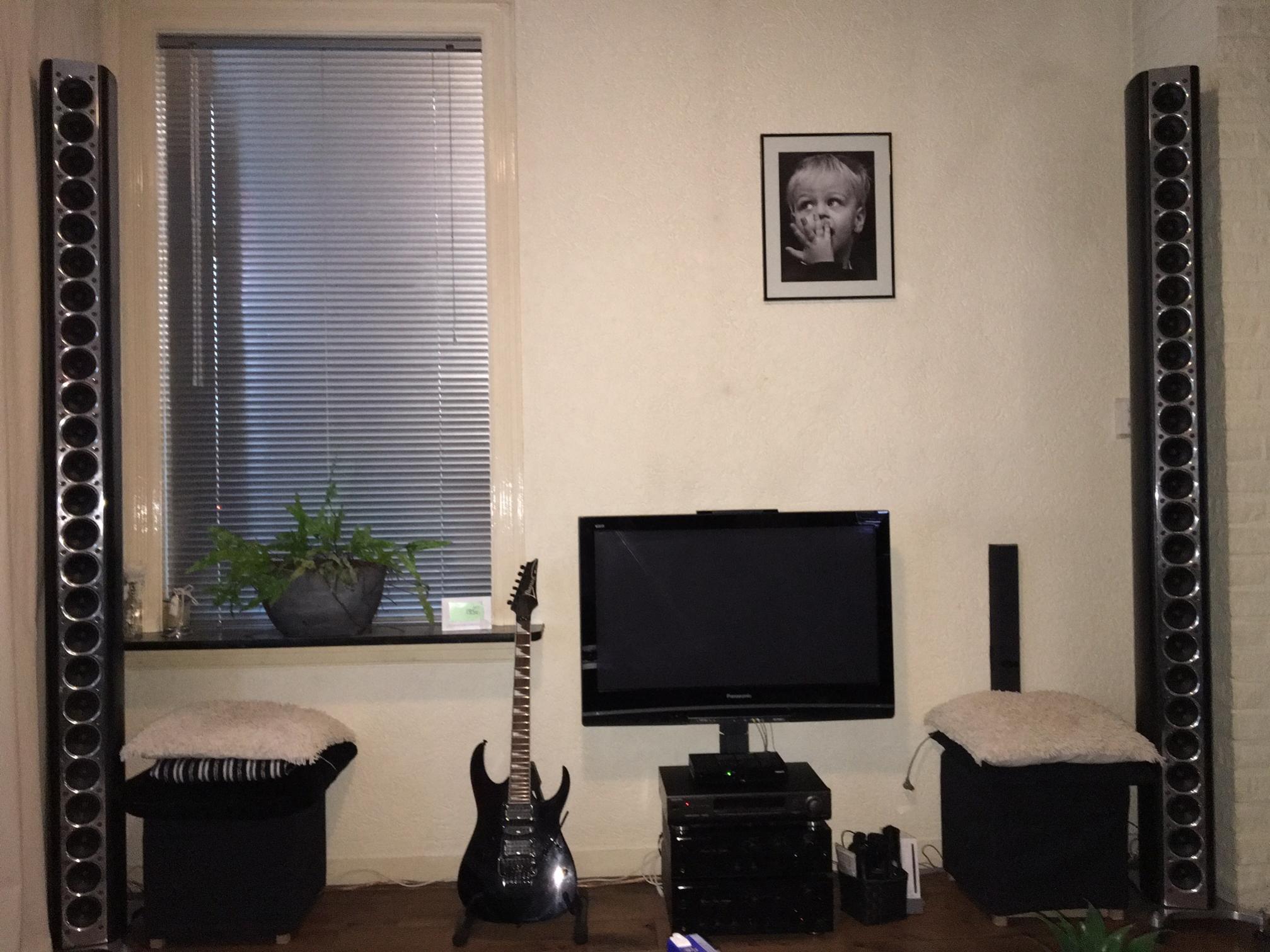
You'll notice the 2 black boxes with cushions. They are feet bench that my girlfriend bought a long time ago and secretively I've measured them to see what I could fit inside of it. It could hold a 12" sealed subwoofer, and I would use a Linkwitz transform on them to get what I need out of it.
Right now they hide my conjugate networks:

Yes... an innocent question
. I'd go for sealed subs for their better time response. A port would always be firing 180 degree out of phase. OB would be an option, but way bigger.If I steal the picture from BYRTT which he took while visiting:
... or the one from xrk971:
You'll notice the 2 black boxes with cushions. They are feet bench that my girlfriend bought a long time ago and secretively I've measured them to see what I could fit inside of it. It could hold a 12" sealed subwoofer, and I would use a Linkwitz transform on them to get what I need out of it.
Right now they hide my conjugate networks:
Last edited:
The sealed option certainly makes sense for best integration with your arrays. I believe someone suggested an Infinite Baffle arrangement. Rather than cutting holes in your wall for the drivers, how about a quasi-IB where you made a false wall between the window and the right corner (looking at your array wall from the couch) that bumped out 15-20 cm (6-8 in) or the same arrangement but behind your couch? I don't recall seeing a photo of the wall opposite the arrays (the couch wall) but that might be a way to accomplish your goals of sub integration with WAF. The enclosure could even be paint-matched to the rest of the room to help it disappear.
I hope your income gets to a level soon enough to allow you to implement whatever solution you settle on but, in the meantime, that gives you the time to thoroughly plot out your design.
I hope your income gets to a level soon enough to allow you to implement whatever solution you settle on but, in the meantime, that gives you the time to thoroughly plot out your design.
Hahaha thanks for thinking "with me". But I have no chance of building fake walls.
As is I praise myself fortunate to have been doing this project without my Girl standing in my way. In fact she has been very supportive in my endeavours but she has put her foot down, saying: no more! No more damping and no more drivers. I can't blame her.
This is just one of many ideas of things I'd like to try. As are a different amplifier and ambient tweeters.
So far I have been able to do a lot of interesting experiments, most of which are documented in this thread. Now I just need to have patience (again) to be able to afford a next instalment.
I think I'd like to start with the weakest link, my amplifier. Rated at 100 watt into 8 Ohm it is the weakest link right now. Especially since the arrays can handle more.
I maxed out the internal digital gain to not leave anything there and keep it just under clipping levels. My DAC is 24 bits, a 32 bit DAC could be another upgrade part in a farther future.
I'm a very happy camper with what I have, it's just curiosity that makes me want to try a bit more. I'm also still trying to find improvement in the DSP part, even though my measurements are impressive if I do say so myself.
As is I praise myself fortunate to have been doing this project without my Girl standing in my way. In fact she has been very supportive in my endeavours but she has put her foot down, saying: no more! No more damping and no more drivers. I can't blame her.
This is just one of many ideas of things I'd like to try. As are a different amplifier and ambient tweeters.
So far I have been able to do a lot of interesting experiments, most of which are documented in this thread. Now I just need to have patience (again
) to be able to afford a next instalment.I think I'd like to start with the weakest link, my amplifier. Rated at 100 watt into 8 Ohm it is the weakest link right now. Especially since the arrays can handle more.
I maxed out the internal digital gain to not leave anything there and keep it just under clipping levels. My DAC is 24 bits, a 32 bit DAC could be another upgrade part in a farther future.
I'm a very happy camper with what I have, it's just curiosity that makes me want to try a bit more. I'm also still trying to find improvement in the DSP part, even though my measurements are impressive if I do say so myself.
I understand the position you are in all too well, Ronald. Many years ago my wife decreed that any additional speakers that I built for home use had to be of furniture-grade quality. No more ugly "permanent prototypes" were allowed in the house. Coming from a cabinetmaker background this wasn't a problem for me, per se, but it did mean much more design planning on the front end instead of experimenting with prototyping of enclosures.
I currently have 2 sets of speakers in my listening room (our den/family room) with another set of monitors in a spare bedroom. My speaker building endeavors now take the form of mainly small footprint full range designs that I make as graduation gifts for certain students at the local school where I work. I like for them to have a decent set of speakers to take to university for use as near-field or PC monitors for their dorm rooms. It keeps me active in the hobby without cluttering up the house with more speakers.
I currently have 2 sets of speakers in my listening room (our den/family room) with another set of monitors in a spare bedroom. My speaker building endeavors now take the form of mainly small footprint full range designs that I make as graduation gifts for certain students at the local school where I work. I like for them to have a decent set of speakers to take to university for use as near-field or PC monitors for their dorm rooms. It keeps me active in the hobby without cluttering up the house with more speakers.
No, the first plot is a measured result of my DAC by routing it's output to my soundcard's line-in with APL_TDA.
The second APL plot is a measurement with mic in sweet spot of my arrays with APL_TDA. As can be seen with the little stuff being upset in my room on the right side of the graph.
Back again and see was wrong reading your plots, which else suited my logic to interpret and explain
those REW waterfalls verse APL_TDA, well well when think about it again understand what you mean and look into the subject, but will probably be tomorrow because has to dig deeper with inpulse tests and find my HDD with APL_TDA installation and hope for its license still works without reactivation because of some hardware change for disks and displays.
Last edited:
I got used to is, but never could figure out the why. There are more of these little things I notice and had to learn about REW. That's why it helps to see "Ideal World" examples from time to time to learn and see how a particular piece of software functions.
The same would be true about any other software package though. As an example, I've often wondered if the tone burst APL uses in it's sweeps is of the same type REW uses.
I just haven't been curious enough to check it.
My way of learning software has always been to try and figure out how it functions (and why). After figuring that out you can do way more with it than if you just learn to use the software. Does that make sense?
I recently stumbled upon this software called Align2. Pretty good software. I ended up not using it but one thing I learned was the minimum phase filter that DRC generates. I have been using that one on the arrays and it sounds a little more relaxed and less phasey. Is this the one you are talking about when you show the linear phase and minimum phase graphs?
I suspect the minimum phase filter probably excludes some things that may cause the filter to sound more phasey or artificial. DRC does so much to extract the loudspeaker response from the measurement that it is hard to tell (for me at least) where the difference is coming from. Or maybe, I'm just hearing what I want to. Haven't done a proper test to see if there really is an audible difference.
Another point that you and I have talked about before is the target response. I use a flat target as advised by Dennis (see section 4.3 in the DRC documentation). But when I was doing this correction on another system in a highly reflective room, the flat target sounded too bright. I had to use a B&K type target in that room. But in my room and on the arrays, the flat target sounds very neutral. I'm curious about your views. I recall that you also use a variation of the JBL curve.
Last edited:
Not entirely, but it does get close.
I use no Excess phase corrections on the top end, but do use it on the bottom end.
What I was getting at in the examples I gave is that you can correct to flat phase. Which gives you the longest flying STEP response. Or see the speaker as a pass band minimum phase device. So I made DRC-FIR correct my phase to follow minimum phase as close as possible. Checking that with the generated phase feature of REW.
If you just set your filter to Minimum phase I can see where the benefit comes from. For me the results with a shorter excess phase window (stopping at 1000 Hz) were a lot cleaner up top. As can be seen in early waterfall plots. So far, everything that cleans up that early waterfall plot seems beneficial to the sound heard.
So I think you heard the same things I did. I just have a different way of getting it. It took me many many tries to get a feeling what variable does what within DRC. I used the predictions to learn it's behaviour and have loads of saved tests in REW to remind me of the differences.
My top end now mimics the Minimum phase setting and I did find that feeling more at ease as well. Except that I used the RePhase tool to do some other minor fixes.
I'm not done after running DRC-FIR. I touch it up with RePhase and several banks of PEQ's in JRiver. I balance my left and right speaker both in frequency and phase.
Even DRC-FIR sometimes tries to overcompensate. I remove any evidence of that I can find and do manual tweaks. I know it's a bit much. I also know it works!
I use no Excess phase corrections on the top end, but do use it on the bottom end.
What I was getting at in the examples I gave is that you can correct to flat phase. Which gives you the longest flying STEP response. Or see the speaker as a pass band minimum phase device. So I made DRC-FIR correct my phase to follow minimum phase as close as possible. Checking that with the generated phase feature of REW.
If you just set your filter to Minimum phase I can see where the benefit comes from. For me the results with a shorter excess phase window (stopping at 1000 Hz) were a lot cleaner up top. As can be seen in early waterfall plots. So far, everything that cleans up that early waterfall plot seems beneficial to the sound heard.
So I think you heard the same things I did. I just have a different way of getting it. It took me many many tries to get a feeling what variable does what within DRC. I used the predictions to learn it's behaviour and have loads of saved tests in REW to remind me of the differences.
My top end now mimics the Minimum phase setting and I did find that feeling more at ease as well. Except that I used the RePhase tool to do some other minor fixes
.I'm not done after running DRC-FIR. I touch it up with RePhase and several banks of PEQ's in JRiver. I balance my left and right speaker both in frequency and phase.
Even DRC-FIR sometimes tries to overcompensate. I remove any evidence of that I can find and do manual tweaks. I know it's a bit much
. I also know it works!I've been getting good results with 1 cycle of EP correction (EPLowerWindow = 4410, EPUpperWindow = 4, and EPFlatType = L) . This is quite a bit weaker up top and a bit stronger on the bottom than the default files. You might notice though as you walk right up to the speakers that the attack of bass instruments gets softer (with exaggerated settings the attacks start sounding like they're playing in reverse), but I've found that this along with linear phase peak limiting (PLType = P) can reduce the "hardness" that can result from sudden phase shifts (I don't think PLType = P would be a good idea with filters much stronger than 4 cycles or so). Anyway, I do think that a min phase filter provides the best "bang for the buck" and is perfectly adequate for enjoying music.
Oh Damn, I just checked in here and what did I miss?? Big speakers, loud music, 17Hz, million mile drives, visits from other countries, great coffee and dowsing each other in gasoline. Good times were had by all, I see!
Thanks for the reports and impressions. Those who have followed this from the beginning, thru the cracked boxes and the DSP wizardry were curious to hear reports. Sounds like a smash hit.
Big speakers, loud music, 17Hz, million mile drives, visits from other countries, great coffee and dowsing each other in gasoline. Good times were had by all, I see!Thanks for the reports and impressions. Those who have followed this from the beginning, thru the cracked boxes and the DSP wizardry were curious to hear reports. Sounds like a smash hit.
I've been getting good results with 1 cycle of EP correction (EPLowerWindow = 4410, EPUpperWindow = 4, and EPFlatType = L) . This is quite a bit weaker up top and a bit stronger on the bottom than the default files. You might notice though as you walk right up to the speakers that the attack of bass instruments gets softer (with exaggerated settings the attacks start sounding like they're playing in reverse), but I've found that this along with linear phase peak limiting (PLType = P) can reduce the "hardness" that can result from sudden phase shifts (I don't think PLType = P would be a good idea with filters much stronger than 4 cycles or so). Anyway, I do think that a min phase filter provides the best "bang for the buck" and is perfectly adequate for enjoying music.
I tried something like that as well. I bet there are differences between getting a single driver to behave or a line array. I'm not that far off from 4 cycles as that does work best all trough the midrange. But even some excess phase correction on top was less clean than not having it at all.
I am a huge believer in "more" correct time behaviour for the low end though. No one can tell me otherwise. I've experienced the differences. I wouldn't want to miss it anymore. It's not particularly beneficial for imaging or staging. I used to think it would help there as well. It's beneficial for the harmonic structures of instruments. The overall tone structure, and if that bottom end is there: the sheer power of it all. Felt and heard in time is addictive for me. More realistic.
More there...
Oh Damn, I just checked in here and what did I miss??
Thanks for the reports and impressions. Those who have followed this from the beginning, thru the cracked boxes and the DSP wizardry were curious to hear reports. Sounds like a smash hit.
Thanks Pano, it was great fun! And I'm glad the sound was worth it
.The best compliments are the "you are there" comments for me.
Like this one:
by xrk971.the immense feeling of being teleported to the recording venue
Last edited:
- Home
- Loudspeakers
- Full Range
- The making of: The Two Towers (a 25 driver Full Range line array)