Your psu transformer position are reverse ( not on front panel side ) and to close with audio inputs and speakers outputs.
Put filter psu caps pcb in this position, reverse amplifier circuits pcs's position as well so your Edcors
are in proximity of rca inputs and far from new psu toroid position.
Take example from photo of First Watt M2 amplifier who work like charm
Edcors are shielded by mu metal screen...enjoy sound from your new diy amplifier.
I've tried with the transformer at the front with the edcors at the back, made no difference.
You connected the Power ground directly to the earth ground bolt. That usually causes a hum. First try to follow Nelson Pass's power supply schematic the best you can (put a CL60 and bridge rectifier between ground and earth), and then see if there is any hum.
Why would I put a bridge rectifier between ground and earth, are they not for turning AC into DC?
I'll put a CL60 from Earth (wire from IEC?) to the chassis ground bolt and get a bridge rectifier if it'll sort it out. Do you not need to use all 4 of the connectors on a bridge rectifier?
I've tried with the transformer at the front with the edcors at the back, made no difference.
What frequency does the humming have?
In your drawing you have connected just one power supply ground to star ground. In reality you connected both grounds (from upper and lower half) of the power supply to the sg, right?
Try to connect all metal parts to safety ground, even if this helps just a bit against hf noise. But it's security wise more than nice to have.
Try to rotate the toroid, if you get lesser humming.
Try to separate low signal wires from power signal wires. Try not to run them in parallel, crossing is OK.
Get all party with high magnetic fields away from those with gentler signals, e.g. toroid and coils from input wires, input transformers,...
Good luck!
PS: Take your time and look at the original First Watt Amps pictures at 6moons, not just the M2's. Try to learn how Nelson connected everything, until you know every wire's beginning and end.
Zen Mod also has many pictures for inspiration and meditation.
Regards,
Matthias
Murdoc post are useful and do you read this basic's article ?
http://www.diyaudio.com/forums/diya...udio-component-grounding-interconnection.html
For all AC psu part please keep original diameter wires like was at toroid output it's all for safety ,
small diameter is only for audio signal.
Yes psu position make difference , screened wires and
....mu metal screen for Edcors
") don't give up after all hard work
don't give up after all hard workjust beacause small imperfections & details.
Twice smile face and learn in the build process
Have fun

Attachments


Last edited:
On your picture the cables carring AC voltages are not twisted, so they could radiate nicely. Just twist them, as you can also see on the big picture soundhappy was so kind to attach. In my own experience there are lot's of smarter brains, so every time I re-check the details of every details (so to speak more than tripple-check) of e.g. 6moon's pictures of Nelson's builds I find a (for me) new details I didn't think of before. We can always see new things (in our lifes) if we had learned the things necessary to see the new ones! And soundhappy is every so right: Don't loose your inspiration and motivation to look for the devils inside your build. The more they annoyed you, the more you enjoy the sound and your triumph afterwards! Good look and have fun! Matthias
PS: The article about grounding soundhappy linked to is the best I know. It is not the shortest there is, but you can learn a lot there, and the best is that this article has no shortcuts which turned into a real build may cause you problems.
PPS: In general you can cluster all these good practices in two categories:
First one tries to eliminate the problem by its root. (E.g.: The signal input should be as short as possible. Is should be located as far as possible from all stronger signals (so everything).
Second one is, as this is all based on natural sciences, or "some" engineer's discipline, a matter of compromises, as every positive thing has its drawback. So, as you sometimes have to route a signal cable cross a power cable, you can: 1: twist the wires 2: use shieled ones 3. minimize the power cables magnetic field (smaller transformer --> smaller charging peak of capacitors, or different configuration of power rectification, e.g. using chokes. 4...1000 If you think about this, it get's easy in general. And if you can't succeed with the first approach, you start using heavier tools.
PS: The article about grounding soundhappy linked to is the best I know. It is not the shortest there is, but you can learn a lot there, and the best is that this article has no shortcuts which turned into a real build may cause you problems.
PPS: In general you can cluster all these good practices in two categories:
First one tries to eliminate the problem by its root. (E.g.: The signal input should be as short as possible. Is should be located as far as possible from all stronger signals (so everything
). Second one is, as this is all based on natural sciences, or "some" engineer's discipline, a matter of compromises, as every positive thing has its drawback. So, as you sometimes have to route a signal cable cross a power cable, you can: 1: twist the wires 2: use shieled ones 3. minimize the power cables magnetic field (smaller transformer --> smaller charging peak of capacitors, or different configuration of power rectification, e.g. using chokes. 4...1000 If you think about this, it get's easy in general. And if you can't succeed with the first approach, you start using heavier tools.
Last edited:
I'll put a CL60 from Earth (wire from IEC?) to the chassis ground bolt and get a bridge rectifier if it'll sort it out. Do you not need to use all 4 of the connectors on a bridge rectifier?
Hi, you can see the connection in Figure 6 here:
https://www.passdiy.com/project/amplifiers/zen-variations-4
Cheers,
Dennis
Just for reference about the hum noise. I just completed my M2 and it is noisier than other amps I have built. The First Watt spec has noise at 500uV 20-20 KHz. Somewhat higher than others in the line up. Most others at 100uV. I have 95 dB back loaded horn speakers. The Hum can be heard when I get within a foot or two of the speaker.
Here's a couple of measurements.
Tea Bag PCB's.
Measured with a Fluke DVM, source connected.
Hum didn't change with or without source connected.
Hum didn't change with PS ground isolated from chassis.
Tried relocating all the signal and power grounds to the star ground on the PS but no change. Went back to the original layout on the Tea Bag PCB's.
0.3 mV AC measured across the speaker terminals with the speakers connected.
20 mV AC of ripple on the power supply.
By rotating the transformer the hum changes with a maximum of 0.5 mV.
If I moved the transformer away as far as the wiring would permit (outside the case) the Hum measured 0.25 mV AC and was quieter and acceptable.
Built a couple of shields from tin cans for the Edcor's but it didn't seem to help much.
One thing I noticed was if I moved the secondary power transformer wiring after the bridge the AC output on the speaker terminals would spike up to 2 mV as I was moving the wires, so obviously its being induced onto the circuit somewhere.
If I can get it down to 0.20 to .25 mV I would be happy.
BDP

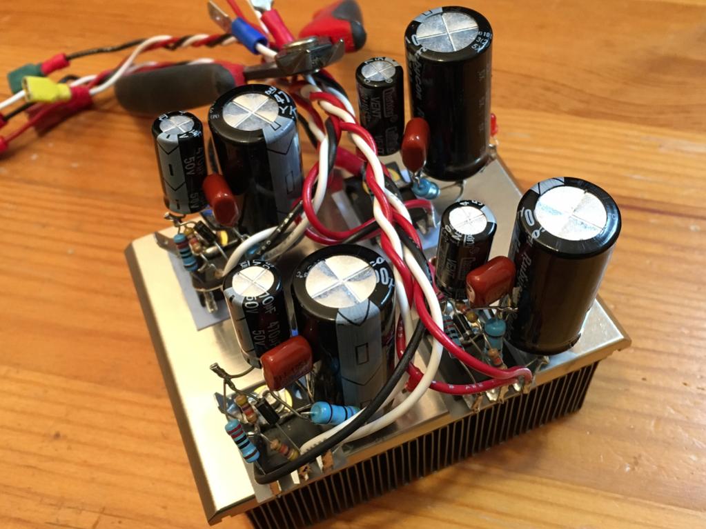
@ BDPHere's a picture of the layout in progress
Do you try hum is lower if you close chassis with his metal cover ??
Wher is your chassis ground connection ?
I always learn a lot with 6L6 build guides photos by courtesy.
Tnx and best regards
Edit : bend your audio input wires into corners direction ( experiment) for little more distance from main AC input.
Attachments


Last edited:
Just for reference about the hum noise. I just completed my M2 and it is noisier than other amps I have built. The First Watt spec has noise at 500uV 20-20 KHz. Somewhat higher than others in the line up. Most others at 100uV. I have 95 dB back loaded horn speakers. The Hum can be heard when I get within a foot or two of the speaker.
Here's a couple of measurements.
Tea Bag PCB's.
Measured with a Fluke DVM, source connected.
Hum didn't change with or without source connected.
Hum didn't change with PS ground isolated from chassis.
Tried relocating all the signal and power grounds to the star ground on the PS but no change. Went back to the original layout on the Tea Bag PCB's.
0.3 mV AC measured across the speaker terminals with the speakers connected.
20 mV AC of ripple on the power supply.
By rotating the transformer the hum changes with a maximum of 0.5 mV.
If I moved the transformer away as far as the wiring would permit (outside the case) the Hum measured 0.25 mV AC and was quieter and acceptable.
Built a couple of shields from tin cans for the Edcor's but it didn't seem to help much.
One thing I noticed was if I moved the secondary power transformer wiring after the bridge the AC output on the speaker terminals would spike up to 2 mV as I was moving the wires, so obviously its being induced onto the circuit somewhere.
If I can get it down to 0.20 to .25 mV I would be happy.
BDP
I think you should try Juma's Easy Peasy Cap Multiplier. It only takes four more IRFP's and a handful of resistors and small capacitors. I added it to a typical FW PSU that has 33mF//0.13R//33mF which has same 20mV ripple as yours, and the ripple went to 0.0mV as measured with a Fluke 101. I was running 1.5 amps on an F5 with SK2013/J313's. The hum was silenced like death after the cap multiplier was added.
You can easily P2P it on the legs of the IRFP like I did or use the nifty PCB layouts folks are making. This is seriously the most bang for your buck. It makes silent passages with blacker blacks and small details, previously not audible, become much clearer.
http://www.diyaudio.com/forums/solid-state/297921-jumas-easy-peasy-capacitance-multiplier.html
Just add the part after the main smoothing caps (2200uF and 4700uF with IRFP and resistors):

Here is what it looks like for both channels (dual rails x 2):
It's not much heat - you could just bolt to bottom panel of amp.
Here is actual test with F5 running 1.5 amps and showing 0mV AC:
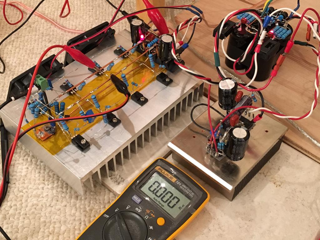
It's so good, I use it in all my amps now. Even a class AB like CFH9:
There is the dropout voltage so you lose 4v (Vgs) from MOSFET drop - your peak power is less. But most listening for me is not peak power limited. You can also spec your trafo +5v higher than usual when ordering for your next project.
My SPICE simulations show that the ripple is about 60uV to 150uV (immeasurable levels with my DVM) and absolutely silent to my ears pressed against the cones.
Last edited:
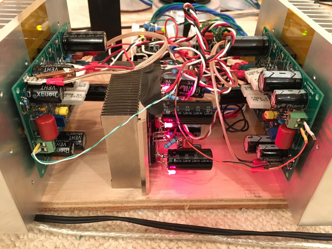
Here's a picture of the layout in progress
In my build shielding the transformer with flexible steel helped more than shielding the Edcor.
The Transformer has an electrostatic shield and magnetic shield. You would think that would do it. I noticed when I elevated the transformer above the steel base plate the hum improved, small improvement but an improvement. More things to try. Years ago my first Pass amp, the A40 needed a steel band around the transformer to quite things down. Wish I would have keep that one. The amp that is.
The hum by no means takes away from listening, can only hear it up close like I said earlier. Listening to some Pink Martini.
At first I used 48 mF per PS rail and had about 60 mV ripple. The factory M2 uses 60 mF and thought maybe that was the issue so I added some more capacitance and upped the R in the RC filter to get me the 20 mV, but it made no difference. The common drain circuits should have good PSRR.
Thanks for the ideas.
I was hoping someone with a factory M2 might stick their DVM on the speaker terminal and give us a number?
The M2 is pretty nice. I haven't found many amps that I like better than the F3. This ones close.
BDP
The hum by no means takes away from listening, can only hear it up close like I said earlier. Listening to some Pink Martini.
I think you should try Juma's Easy Peasy Cap Multiplier.
At first I used 48 mF per PS rail and had about 60 mV ripple. The factory M2 uses 60 mF and thought maybe that was the issue so I added some more capacitance and upped the R in the RC filter to get me the 20 mV, but it made no difference. The common drain circuits should have good PSRR.
Thanks for the ideas.
I was hoping someone with a factory M2 might stick their DVM on the speaker terminal and give us a number?
The M2 is pretty nice. I haven't found many amps that I like better than the F3. This ones close.
BDP
Murdoc post are useful and do you read this basic's article ?
http://www.diyaudio.com/forums/diya...udio-component-grounding-interconnection.html
For all AC psu part please keep original diameter wires like was at toroid output it's all for safety ,
small diameter is only for audio signal.
Yes psu position make difference , screened wires and
....mu metal screen for Edcors
just beacause small imperfections & details.
Twice smile face and learn in the build process
Have fun
Thanks for the advice, link and encouragement. I've swapped the transformer and psu around, ordered some heavier wire to go between IEC socket and transformer (would twisting this help) and between transformer secondaries and psu board (which I'll twist, thanks Murdoc). I've crossed power wires at 90 degrees to each other (eg IEC to transformer wires are at 90 degrees to M2 board to psu board wires). My input and output wires are at the top of the case and away (as much as possible) from each other.
I've connected a CL60 between IEC earth tab and star ground, connected transformer earth/ground (? not sure which terminology is correct and this is causing some some confusion) to star ground and finally psu ground to star ground.
My star ground is connected to the chassis. Is this correct so far? I'll post pictures when I get the new wiring installed.
If I still have an intrusive hum I'll fit MuMetal shields to the Edcors (where is best to get Mumetal in the UK?).
I really appreciate the help, when I can ignore the hum it sounds stunning!
how on earth ppl don't get first and most basic thing :
IEC earth tab must go directly to chassis
then main audio GND point goes through CL60 to same point on chassis
after that - whatever you do is sound issue , but safety issues are covered
if needed - you can replace that CL60 with short or with diode bridge in parallel with CL60 , depending of actual needs
Last edited:
That's what I've done, I was looking for confirmation. The switching between terms of earth and ground is a bit confusing.
It's what I've done in the other bits of kit I've built but in this thread I've read chassis ground, star ground etc and it confuses things when you're lacking confidence due to a mess up months ago.
It's what I've done in the other bits of kit I've built but in this thread I've read chassis ground, star ground etc and it confuses things when you're lacking confidence due to a mess up months ago.
Anybody had any issues with AnTek shipping transformers to Texas? I can't check out, when I enter just the Country, State, Zip to estimate shipping it says they won't ship here.
They have always used Fedex for all my orders and you are right Fedex does not deliver everywhere. I know this from working in a shipping warehouse a few years back. Give them a call and I bet they will arrange alternate shipping. Good folks.
They have always used Fedex for all my orders and you are right Fedex does not deliver everywhere. I know this from working in a shipping warehouse a few years back. Give them a call and I bet they will arrange alternate shipping. Good folks.
Strange. They have always used USPS Priority Mail for my orders.
Anybody had any issues with AnTek shipping transformers to Texas? I can't check out, when I enter just the Country, State, Zip to estimate shipping it says they won't ship here.
I have at least 6 from Antek here. No shipping issues on any. All were usps priority mail. They do respond to email. I've ordered transformers listed as out of stock on their site via email a couple times.
- Home
- Amplifiers
- Pass Labs
- Official M2 schematic