Hello Everybody.
Let me share with you a concept that I am fiddling around with recently.
Code name: "ZiggyReg", version 2.0. (Shiklai bipolar).
The first, early version V.1.0. was based on the IRF540 mosfets.
The device is a combination of a series and shunt regulator. A bit of both at the same time. Anyways, the more I am fiddling with it, the more I am under the impression that it seems to work.
At least as far as I can tell with my universal multimeter (static conditions).
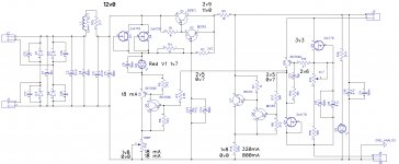
The output voltage may be set by a potentiometer, the one on the far right of the schematic. The actual proportion of how much "shunt" there is augmenting the "series" - can be set by an additional potentiometer, the one at center down below. Depending on the proportion of shunt and series, it seems that it is possible to set a negative impedance on the output, or a positive impedance on the output, or something in between.
Anyways, I am hoping that you will help me out with a few details.
a). The Zobel R10 + C12 is currently not included in my circuit. I do not have skills and apparatus to diagnose, is it absolutely necessary, and if the of-the-top-of my head values are correct for the R+C.
b). The current circuit that I am fiddling with does not yet have C13||C14 and R4. So in other words, both the series and the shunt legs are "equally quick" to react, within the preset proportion of their engagement. Question: Will there be added value in adding C13||C14 and R4 ? These are envisioned as a slow-start and capacitance multiplier for the series leg. But that would also imply a "slowly adapting" series leg, and a "quickly reacting" shunt leg. What would be better? When they are both "quick", or when one is used as a soft-start and capacitance multiplier (of sorts)?
c). For initial testing, the collector of Q7 was supplemented by a 330mA 1W LED, which served the purpose of a "visual" status representation. But the circuit seems to be much better off without it. Actual current of the shunt leg may be determined by the voltage drop on R13.
d). R11 - is purely "intuitive". The element, as well as its actual value, are gut-feeling based. Indeed, it seems to be needed there, as the circuit behaves less reasonably when R11 is shorted out. Intriguing. Any comments on that ?
e). If there are indeed no oscillations on the output of this contraption (a thing which I am not capable of reasonably determining) - do you foresee any useful applications for such a regulator: four-wires, with sensor pair, capable of negative output impedance (as it seems for some bizarre reason) ?
Your comments - kindly welcome.
With 12VDC on the input (bridge bypassed), it is possible to set output voltages ranging from 2,9V to 11,0V, and these still within proper regulation range.
With the series to shunt proportion regulator, it is possible to set the shunt current from practically zero to a few hundred milliampere.
For example:
If I set the output voltage to 5,00 volts (at low load), and the load is switchable between "low load" = 22 ohms and high load = 22 || 22 = 11 ohms, then provided that the shunt current is at least half the value of the input current entering from the input side of the regulator, then for "high_load" conditions, I can set for any of the following output voltage scenarios:
.... 4,90V; 4,95V; 5,00V; 5,02V; 5,06V; 5,10V ...
In other words, If during low current draw condition output voltage is 5,00V, then under twice the current draw conditions (22R||+22R) it is possible to achieve an output voltage of exactly 5,00V. Unless, that is, one prefers to have 5,01V.
Does this make any sense to you?
Do you envision any beneficial applications for such?
Comments - kindly welcome.
Cheers,
Ziggy.
Let me share with you a concept that I am fiddling around with recently.
Code name: "ZiggyReg", version 2.0. (Shiklai bipolar).
The first, early version V.1.0. was based on the IRF540 mosfets.
The device is a combination of a series and shunt regulator. A bit of both at the same time. Anyways, the more I am fiddling with it, the more I am under the impression that it seems to work.
At least as far as I can tell with my universal multimeter (static conditions).
The output voltage may be set by a potentiometer, the one on the far right of the schematic. The actual proportion of how much "shunt" there is augmenting the "series" - can be set by an additional potentiometer, the one at center down below. Depending on the proportion of shunt and series, it seems that it is possible to set a negative impedance on the output, or a positive impedance on the output, or something in between.
Anyways, I am hoping that you will help me out with a few details.
a). The Zobel R10 + C12 is currently not included in my circuit. I do not have skills and apparatus to diagnose, is it absolutely necessary, and if the of-the-top-of my head values are correct for the R+C.
b). The current circuit that I am fiddling with does not yet have C13||C14 and R4. So in other words, both the series and the shunt legs are "equally quick" to react, within the preset proportion of their engagement. Question: Will there be added value in adding C13||C14 and R4 ? These are envisioned as a slow-start and capacitance multiplier for the series leg. But that would also imply a "slowly adapting" series leg, and a "quickly reacting" shunt leg. What would be better? When they are both "quick", or when one is used as a soft-start and capacitance multiplier (of sorts)?
c). For initial testing, the collector of Q7 was supplemented by a 330mA 1W LED, which served the purpose of a "visual" status representation. But the circuit seems to be much better off without it. Actual current of the shunt leg may be determined by the voltage drop on R13.
d). R11 - is purely "intuitive". The element, as well as its actual value, are gut-feeling based. Indeed, it seems to be needed there, as the circuit behaves less reasonably when R11 is shorted out. Intriguing. Any comments on that ?
e). If there are indeed no oscillations on the output of this contraption (a thing which I am not capable of reasonably determining) - do you foresee any useful applications for such a regulator: four-wires, with sensor pair, capable of negative output impedance (as it seems for some bizarre reason) ?
Your comments - kindly welcome.
With 12VDC on the input (bridge bypassed), it is possible to set output voltages ranging from 2,9V to 11,0V, and these still within proper regulation range.
With the series to shunt proportion regulator, it is possible to set the shunt current from practically zero to a few hundred milliampere.
For example:
If I set the output voltage to 5,00 volts (at low load), and the load is switchable between "low load" = 22 ohms and high load = 22 || 22 = 11 ohms, then provided that the shunt current is at least half the value of the input current entering from the input side of the regulator, then for "high_load" conditions, I can set for any of the following output voltage scenarios:
.... 4,90V; 4,95V; 5,00V; 5,02V; 5,06V; 5,10V ...
In other words, If during low current draw condition output voltage is 5,00V, then under twice the current draw conditions (22R||+22R) it is possible to achieve an output voltage of exactly 5,00V. Unless, that is, one prefers to have 5,01V.
Does this make any sense to you?
Do you envision any beneficial applications for such?
Comments - kindly welcome.
Cheers,
Ziggy.
Attachments
I have discussed the concept, which I dubbed "tandem regulators":
http://www.diyaudio.com/forums/power-supplies/265435-tandem-regulators.html
I had the intention of discussing all possible alternative topologies, but it has been cut short.
I show the "canonical" form, as simple as possible for easy comprehension, but they could be sophisticated.
In the mean time, I have explored another class of these regulators, completely different but barely more complicated, and of extreme performance.
I may publish it some day, but not necessarily here
I understand the concept of such a thing. But I believe that it can be much more easily implemented around any kind of DC coupled amplifier (transistorized or chip) like, as an example, the humble TDA2006 and similar. Taking the NI from a reference voltage, and with proper output to I input wiring, it can be the same task, with lower costs.
My opinion only.
My opinion only.
Thank you for your comments.different but barely more complicated, and of extreme performance. I may publish it some day, but not necessarily here
Maybe just a quickie helper question: is it possible that your way of thinking evolved in the direction towards a reprogrammable, slowly, but self adapting input side current source? Just curious, as that would be the direction for my V. 3.0, if I ever get to that stage ...
Thanks for the hint. Will look into that.... as an example, the humble TDA2006 and similar. Taking the NI from a reference voltage, and with proper output to I input wiring, it can be the same task, with lower costs.
My opinion only.
Member
Joined 2006
www.diyaudio.com/forums/power-supplies/164365-class-preamp-psu.html
Is this of something similar?
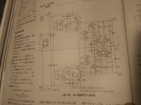
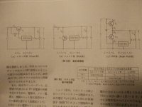
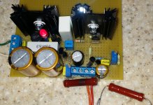
If so, the earliest published design i have seen was from the April 1984 issue of MJ magazine. See photos attached.")
It was called a push pull design.
The shunt and series transistors are responsible for the correction of the + and - output voltage variation, respectively.
Is this of something similar?
If so, the earliest published design i have seen was from the April 1984 issue of MJ magazine. See photos attached.
It was called a push pull design.
The shunt and series transistors are responsible for the correction of the + and - output voltage variation, respectively.
Attachments
Last edited:
Yes, indeed, very very intriguing. The original Japaneese design that you have shown seems to be in need of a complementary pair of push-pull transistors, and indeed they do resemble a true push-pull.www.diyaudio.com/forums/power-supplies/164365-class-preamp-psu.html
Is this of something similar?
If so, the earliest published design i have seen was from the April 1984 issue of MJ magazine. See photos attached.
It was called a push pull design.
The shunt and series transistors are responsible for the correction of the + and - output voltage variation, respectively.
The thing that I skeched up is based on two identical transistors, in this case, NPN and NPN, each od them Shiklai driven by PNP and PNP, but in terms of the way it "functions" - it seems to be the same thing.
I do not use a bias spreader, because I do not need one. Instead, I came up with a "Y" forked feedback loop, whereby the very same feedback signal feeds into two distinct control sub-circuits. In some funny way, I came up with a version where the complementary transistors are not needed, but rather transistors of same polarity.
Very intriguing, the Japanese design.
Also I would like to thank you for drawing my attention to the Class A preamp PSU design. That shall definitely be an interesting read for me.
Thanks.
Ziggy.
Question: in this push pull design: how much push is there with respect to pull ?It was called a push pull design.
If this is based on a "bias spreader" approach, then is it correct to assume that the thing works like a 50% / 50% mirror, as in a typical "push-pull" amplifier output stage?
The reason that I am raising this ... is that the thing that I came up with gives you the freedom to choose.
Not only just the 50%/50% option.
But you can adjust, vary this proportion, according to whatever preference you wish.
Ranging from 100% push / 0% pull, ...... up to 1% push and 99% pull. (and any values in between)
This seems to be the crucial discriminating factor, as I think I understand it.
Last edited:
Member
Joined 2006
I stand corrected. You caught me red handed in my haphazardness. It is a relict/byproduct of my musings as to just "how low can it go" - a relict from my mental debating as to if it will be at all possible to go as low as 3v3 with the output voltage, kind of like mentally being reverse engineered back from the output to the Vbe drops and the saturation voltages and all.Just curious, where do you find 3v3 in the upper right corner ?Mona
The initially considered application for this "device" was a source of 3v3 for the digital circuits of a DAC. I was hoping to go as low as 3v3 with this device, and hoping to achieve a "flat output", unchanging voltage, when facing fast and significant, "digital" changes of the output current load.
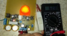
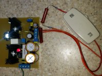
As it turns out, the regulator can be trimmed down to 2v9 which seems to be the lowest reasonable setting practically achieveable. So 3v3 is a piece of cake, as it turned out (after getting rid of the 330mA 1W power led, that was inserted on top of the shunt power transistor and served as a "visual control" of the quantity of shunt current).
As mentioned, the prototype looks like below. And the more I test it, the more I am under the impression that it works. But what I am lacking isYours is intriguing too with a higher degree of adjustability.
Hope you will finalize the design and test it out with a preamp etc soon.
a). SPICE analysis of the transients / dynamics, and
b). a sneaky way to emulate digital load transients on the load, and how to "visualize" them on a 2 channel scope.
I would reckon that I need a load resistor, and a second load resistor being "keyed" by a transistor, the base of which receives a square wave of some sort. ... but that is easier said than done, as this square wave would need to have very steep edges, so that the scope could pick up any ringing on the transients, no ?
The schematic in post #1 includes four 2SK170 JFETs, each with its gate tied to its source, operated as constant current sources. These devices are out of production, difficult to find, and (if you do manage to locate non-counterfeit devices) quite expensive. Couldn't you use a current-production, widely available, low priced JFET instead? Perhaps a Fairchild J112 with source degeneration resistor, or (diyAudio's favorite device) an NXP BF862 with source resistor?
You are absolutely correct.The schematic in post #1 includes four 2SK170 JFETs, each with its gate tied to its source, operated as constant current sources. These devices are out of production, difficult to find, and (if you do manage to locate non-counterfeit devices) quite expensive. Couldn't you use a current-production, widely available, low priced JFET instead? Perhaps a Fairchild J112 with source degeneration resistor, or (diyAudio's favorite device) an NXP BF862 with source resistor?
Depending on local availability, it would be prudent to choose the j-fet devices that you have mentioned.
The reason that I depicted the 2sk170 is multifold:
a). I am using DipTrace drawing tool, with only but basic libraries of elements listed. So I put these very "well known" 2sk170 devices into the schematic - as a placeholder of sorts - partially because they are simply available in the DipTrace libraries.
b). Within this circuit, I actually consider these J-Fets as 'non-critical' elements. As long that they work properly - what would be the reason to seek for "originals"? The main thing that need be taken under scrutiny is that they do have a reasonable voltage handling resiliency between drain and source, at zero gate bias conditions ... and that they have a zero bias conditions current which is inline with what is actually needed.
b). ... and this brings me to the (most probably?) Asian replicas of the 2sk170, which are available out here; They are called "K170" are dirt cheap on our local auctions. Something like 50 cents a pop. Please check out this link (our local Polish "ebay" alternative):
[EURO] 2SK170 2SK170-BL tranzystor FET za 2,50 (6541496378) - Allegro.pl - Wi?cej ni? aukcje.
[ELMAG] 2SK170 N-FET tranzystor 1,70 z?/szt. (5984804869) - Allegro.pl - Wi?cej ni? aukcje.
2SK170BL TO92 NFET 40V 20mA 9W GEMBARA (6374074651) - Allegro.pl - Wi?cej ni? aukcje.
or in general, the "current" search results:
2sk170 - Allegro.pl - Wi?cej ni? aukcje. Najlepsze oferty na najwi?kszej platformie handlowej.
Please take note that 1 USD =~ 4 PLN. So if it costs 2 PLN, it is basically 50 cents. Some of the auctions are organized in batches,
Maybe my way of looking at this is scewed , but I am only but a humble DIY guy, and I do not foresee series production manufacturing of anything in the foreseeable future. So "current production" is not a burning issue for me. Rather the here and now availability of a few units, that I may need for my next upcoming DIY project.
Last edited:
What is the reason that this particular device is a "favorite"?.... , or (diyAudio's favorite device) an NXP BF862 with source resistor?
What are it's strengths, in a nutshell ?
BF862: very low noise, very high gm and (gm/C), high Idss, low cost, wide availability.
This Linear Audio article, written by a diyAudio member, shows the BF862 in action.
This Electronics Design magazine article, written by another diyAudio member, shows a test of several JFETs. BF862 is the winner.
This Linear Audio article, written by a diyAudio member, shows the BF862 in action.
This Electronics Design magazine article, written by another diyAudio member, shows a test of several JFETs. BF862 is the winner.
Agree with Mark, save your precious 2SK170 Jfets for different duty
Anyway, using short gate, high gm Jfet alone as CCS is not good choice. It is better to use cascode, but then you will need higher voltage across it to get Vdg > 2 x Vgs(off). See Siliconix App Note AN103.
Anyway, using short gate, high gm Jfet alone as CCS is not good choice. It is better to use cascode, but then you will need higher voltage across it to get Vdg > 2 x Vgs(off). See Siliconix App Note AN103.
Nice read indeed, that application note.Anyway, using short gate, high gm Jfet alone as CCS is not good choice. It is better to use cascode, but then you will need higher voltage across it to get Vdg > 2 x Vgs(off). See Siliconix App Note AN103.
Actually, this cascode looks very similar to the cascoded DN2540 "power" versions that I have been using for the anodes of some of my vacuum tube stuff just recently. But I sort of missed out on the similarity between the j-fets at hand and the DN2540 ...

Now that you have mentioned it - indeed, it seems like very obvious.
The cascode version is a thing that I could put to a good use in the context of this regulator. On the input side, If I understand correctly, it would be just a matter of agreeing to a slightly greater overall minimum required dropout voltage. On the sensor side - such cascode can also be put to a good use - especially in such cases, where there is no requirement to go way way down low with the output voltage, to say a 3.3V DC output voltage scenario.
My gut feeling tells me that when fully cascoded, the regulator should be capable of delivering a nice 5,0V output voltage, and that with a good reserve of regulation breathing margin.
- Status
- This old topic is closed. If you want to reopen this topic, contact a moderator using the "Report Post" button.
- Home
- Amplifiers
- Power Supplies
- A Series-Shunt regulator: The "ZiggyReg V 2.0"