GU50 ultralinear
I did the GU50 ultralinear. I forget what bias voltage I used on the grids, but I used 400 volts or just under 400 volts and I used a 5K resistor on the screens. It functioned fine. MANY hours on it and no problems.
Yes, you can wire two 6-volt heaters in series. I do it all the time and never had an issue. as long as they are the same type of tube.
Last edited:
I used a 5K resistor on the screens.
This is too high value. Available output power is strongly limited, because the screen current is limited.
I made a quick simulation (with 350 v supply voltage) and varying screen grid resistors
to 100 ohms and 5k.
Output power with 100 ohms is 35 W and with 5k just 20 W.
you may be right, but that is what the German data sheet called for, a 5K screen grid resistor, if you raise the screen voltage over 250, which UL would do. in the FWIW dept, I did not make power measurements, but I did fiddle with different resistors and didn't seem to make any difference. I even used a voltage divider network out of paranoia to keep the screen voltage around 300 and it still worked fine.
what I did notice is that it required 70 ma or more quiescent current to sound good, didn't sound so great with 50 or 60 ma. Built that amp years ago, so exact details aren't fresh in my mind anymore. I must say, it was one of the best sounding amps I ever heard.
and 350 volts didn't work. I had to get the voltage up to 400 volts before it sounded good.
Last edited:
In EL152 (similar to GU50) triode connected specs the max. andode (and G2 voltage too) is 400 V so there is no reason to worry about the tube life provided that the max. anode dissipation is not exceeded.
Here is the data, see page 10.
http://www.mif.pg.gda.pl/homepages/frank/sheets/118/e/EL152.pdf
Here is the data, see page 10.
http://www.mif.pg.gda.pl/homepages/frank/sheets/118/e/EL152.pdf
well, you opened up a whole can of worms there. Forced me to do some research as I seem to recall articles on the EL34 stating that it was better with 1200 ohms or 2 Kohms than the much more common 470. The 5K resistor called for in the German data sheets rather surprised me; it seemed a bit high.
I posed this question and never did get an answer: what makes the screen so much different than the control grid? In some cases, the screen is used as the control grid, i.e, signal applied. I built a few amps "screen drive" and they sound great.
So, I was measuring the voltage across the screen resistor and saw either no or miniscule voltage drop. I think I settled on 1 Kohm.
And when you look at the situation, there are usually other resistors (pentode mode) upstream from the screen grid (power supply), so you realistically have to consider them as well.
I don't see why there has to be screen current, per se. It seems that the screen serves to accelerate electrons and, as long as the proper voltage is present, it should serve that function. current diverted through the screen is power lost not power gained. Not trying to be argumentative, but would love to see this explained authoritatively. I recognize that one wouldn't want a value so great that current flow thru the screen resistor would cause enough voltage fluctuation to destroy sound quality or drop enough voltage to reduce power output
> the German data sheet called for, a 5K screen grid resistor
Can you point to the sheet and page which says that?
The Telefunken sheet page 7 gives Rg2 of 5K; but for "schirmgittermodulation" which is "screen grid modulation", a radio transmitter working Class C. This also gives Rg1 as 5K, which is an easy DC limit for RF amplifiers but real annoying for R-C coupled audio power amplifiers. Page 6 shows similar for suppressor grid modulation, again in class C.
I bet 5K may be an upper limit before output really falls off. As a dynamic audio amplifier it may have what guitarists call "sag" (depending where the bypass cap is). I didn't calculate, but 1K seems ample to me. In overdriven guitar, 1K may be "needed" so the screens sag and don't heat too much in heavy clipping. In a "clean" amp which hardly ever clips, a hundred Ohms just to burn in-case the tube gets an internal short.
And yes, if you like bias at -40V you will need the opamp which can eat 88V (+/-44V) at least.
@RateReducer:
I did a spice sim for your new circuit w/6SN7 + GU50 Ayumi model:
- 1st stage (2-triode cascode) has gain of 56x
- 2nd stage (2-triode LT-phase-splitter) has gain of 7x
- output stage (GU50's + OPT) gain is close to unity
- total open-loop gain therefore approx. 400x (52dB)
- closed loop gain (AP and FB pot in middle) approx. 24x (27dB)
- 21V rms output into straight 8 ohm resistive load with 0.85V rms input at clipping
- so a little over 50 watts
- drive signal into GU50 grids under these conditions 80V peak-to-peak (!)
- frequ. resp. 10Hz...100kHz (w/simple transformer model)
- flat w/ resistive load, 0.5dB ripple w/ 2-way speaker model
- sim THD 0.05 ... 0.2% (will be higher in reality)
- there is a rather nasty peak in the bode plot at HF depending on leakage ind. of OPT
which could cause RF oscillation with larger FB when loop is closed
(can be tamed though, will see when it happens ...)
power up the amp 1st without any FB and input shorted, measure / adjust DC values;
use dummy load and oscilloscope on output, make shure there's no oscillation;
then close FB loop and check that still no oscillation (can be as high as 1MHz);
recheck DC values
Last edited:
LS50 datasheet for GU50
the LS50 Telefunken data sheet, section 7, 9, and 10 all make reference to the 5K resistor for the screen grid Schirmgitter
In looking at this topic more in depth, improved sound quality is claimed up to about 1200 ohms. Specifically on an EL34 amp. The "normal" or usual 470 ohms was considered to be a "stab in the dark" guess, and more testing settled on something like 1200 ohms.
I was operating on the thesis that if I didn't measure much voltage drop across that resistor, it should be fine. I think I saw only like a volt at most. it's been many many months since I built a screen drive amp, so, details are bit fuzzy. The last screen drive amp I built was really spectacular in terms of sound quality, so obviously the 1K resistor I used wasn't hurting
I'm thinking 1K to 1200 ohms from now on then?
> the German data sheet called for, a 5K screen grid resistor
Can you point to the sheet and page which says that?
The Telefunken sheet page 7 gives Rg2 of 5K; but for "schirmgittermodulation" which is "screen grid modulation", a radio transmitter working Class C. This also gives Rg1 as 5K, which is an easy DC limit for RF amplifiers but real annoying for R-C coupled audio power amplifiers. Page 6 shows similar for suppressor grid modulation, again in class C.
I bet 5K may be an upper limit before output really falls off. As a dynamic audio amplifier it may have what guitarists call "sag" (depending where the bypass cap is). I didn't calculate, but 1K seems ample to me. In overdriven guitar, 1K may be "needed" so the screens sag and don't heat too much in heavy clipping. In a "clean" amp which hardly ever clips, a hundred Ohms just to burn in-case the tube gets an internal short.
.
the LS50 Telefunken data sheet, section 7, 9, and 10 all make reference to the 5K resistor for the screen grid Schirmgitter
In looking at this topic more in depth, improved sound quality is claimed up to about 1200 ohms. Specifically on an EL34 amp. The "normal" or usual 470 ohms was considered to be a "stab in the dark" guess, and more testing settled on something like 1200 ohms.
I was operating on the thesis that if I didn't measure much voltage drop across that resistor, it should be fine. I think I saw only like a volt at most. it's been many many months since I built a screen drive amp, so, details are bit fuzzy. The last screen drive amp I built was really spectacular in terms of sound quality, so obviously the 1K resistor I used wasn't hurting
I'm thinking 1K to 1200 ohms from now on then?
Last edited:
> section 7, 9, and 10
The Telefunken EL152 data re-formatted. Again, these are modulated RF SE stages. Modulation is non-linear, and some G2 resistance may cap the rise of audio gain toward 100% up-modulation. Meanwhile the tube is being swing over the *entire* current range by being over-driven with MHz RF.
Working as linear amp in push-pull makes some of these techniques less critical.
Conventional G1 drive is not-quite same as G2 drive. Different not only in the large difference of voltage and Power needed, but G2 effects do not quite track G1 effects (Mu(g2) is not constant).
I've always felt that "best" audio operation (G1 drive) is with G2 fed from low impedance.
In data from TV H-sweep operation (and experience in guitar amps) some G2 resistance (~~~1K), increasing with supply voltage, reduces G2 abuse and tube life.
Drawbacks of "too large" Rg2 may include lower gain and lower output. If you are doing experimental work, that's all fine and something to experiment on.
G2 resistor
A few years ago when I was debating making a GU50 ultralinear, somebody or bodies on the forum said "impossible" because of the low voltage for G2 the data sheets espoused. SO, I was very careful about it. The data sheets were actually a bit confusing to me as the figure of 250 to 300 volts was given repeatedly. but there was that part about triode mode and 400 volts. So, I first built the voltage divider from the UL tap to ground and came off that for the screen and it worked okay. Then, I took out the divider and just let a screen resistor in and it was okay. I have seen many references to degraded sound quality with G2 resistor too big (yesterday while researching this topic)
the only tubes I lost were because of a those chinese sockets and an error I made on G3 to ground. No tubes lost because of screen voltage too high. I'm guessing those data sheets aren't as helpful as they could be since they seem to be all about RF and not audio.
I found one thread where the banter suggests that the ideal screen resistor value depends on the tube - this in reference to G1 drive only.
Two of the best sounding amps I built were using TV sweep tubes, old cheap OPTs and probably 1K for the screen resistor.
I was going to redo the GU50 and try screen drive just for the hell of it, although I have UL OPTs for it. So, before I do that, I will try it with a small value screen resistor and see what happens. I'm curious about screen drive because sound quality was pretty poor until the B+ was 400 volts - lower voltage was really sad-sounding.
I was operating under the assumption that if Anode voltage was well above screen voltage, the current flow should naturally seek out the anode and very little screen current should ensue. I am puzzled by those who assert that the screen MUST have significant current flow for decent sound, when the measurements I was taking showed very little current flow even with smaller screen resistors.
> section 7, 9, and 10
I've always felt that "best" audio operation (G1 drive) is with G2 fed from low impedance.
Drawbacks of "too large" Rg2 may include lower gain and lower output. If you are doing experimental work, that's all fine and something to experiment on.
RE: Low impedance: One screen drive amp that sounded really good, really lush sound, I used overkill pentodes for drivers. The anode resistor being a fairly low value, as I recall. Is that why it sounded so good? I was thinking to use MOSFET buffers in the future for this sort of thing.
I also did a PPP amp about 5 years ago. it was UL. did not work until I added screen resistors - I used the "standard" 470 ohms. that too was a very nice sounding amp just using the cheap 6P3S. a tube amp aficionado wanted me to sell it to him.
I found very little info on screen drive and ended up kinda winging it. I didn't like the couple of designs I saw out in internet land
Hi.
So i rebuilt the amp...
Using tubes as prestage the amp finally sounds good.
But there is a new major problem - hum.
When the volume pot is at minimum the hum is really loud...
Turning the pot to the right the hum nearly disappears at a certain position of the pot. Turning it more to the right the hum comes back...
Do guys have some ideas how i could get rid of the stupid hum?
I tried to run the heaters on DC but it did not get better.
So i rebuilt the amp...

Using tubes as prestage the amp finally sounds good.
But there is a new major problem - hum.
When the volume pot is at minimum the hum is really loud...
Turning the pot to the right the hum nearly disappears at a certain position of the pot. Turning it more to the right the hum comes back...
Do guys have some ideas how i could get rid of the stupid hum?
I tried to run the heaters on DC but it did not get better.
There was a thread about hum depending on vol pot position, but I am not shure whether it had a resolution by then. Anyhow, here it is: http://www.diyaudio.com/forums/tube...um-if-volume-knob-max-zero.html?highlight=hum
Hum max in middle of pot is understandable if we assume hum gets injected into 1st tube's grid; if pot at zero, grid is shorted to gnd; if pot at max, grid is shorted to signal source which is also low impedance; so hum is max in between.
I have also seen such hum when amp had HF oscillation; check w/osci timebase set to high freq. Also recommend grid stoppers on all tube grids, 1k for power tubes, 10k for small signals, close and short to grid pins. Fix that first if necessary.
Next is star grounding, separate wire from every input related gnd to a central gnd point, the selection of which may be crucial. Special attention to bottoms of C1, Pot, R3, spkr gnd; any loop here will produce hum.
What value is vol pot ? 1 Meg would be too high.
Does hum also depend on position of FB pot ?
Using shielded wires anywhere? If so make shure shields are grounded only on one end, not both and not used to carry any currents or connecting gnd points.
Wire from pot wiper to grid may require shielded cable - even if short - if it runs anywhere near trafo or heater wires (despite of twisting).
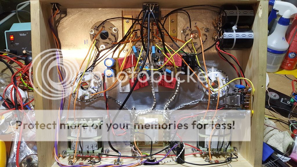
Is that a metal box or wood ?
Complete schematics - your version - inc. power supply will help the discussion tremendously; if possible indicate grounding plan.
Hum max in middle of pot is understandable if we assume hum gets injected into 1st tube's grid; if pot at zero, grid is shorted to gnd; if pot at max, grid is shorted to signal source which is also low impedance; so hum is max in between.
I have also seen such hum when amp had HF oscillation; check w/osci timebase set to high freq. Also recommend grid stoppers on all tube grids, 1k for power tubes, 10k for small signals, close and short to grid pins. Fix that first if necessary.
Next is star grounding, separate wire from every input related gnd to a central gnd point, the selection of which may be crucial. Special attention to bottoms of C1, Pot, R3, spkr gnd; any loop here will produce hum.
What value is vol pot ? 1 Meg would be too high.
Does hum also depend on position of FB pot ?
Using shielded wires anywhere? If so make shure shields are grounded only on one end, not both and not used to carry any currents or connecting gnd points.
Wire from pot wiper to grid may require shielded cable - even if short - if it runs anywhere near trafo or heater wires (despite of twisting).
Is that a metal box or wood ?
Complete schematics - your version - inc. power supply will help the discussion tremendously; if possible indicate grounding plan.
Last edited:
Hi.
Thanks for the answers.
@payload: -> 50k pot.
I have installed shielded wires from cinch input to the pot to the pre stage to G1 of GU50 and implemented star ground. I grounded the chassis of the amp. I increased the negative feedback.
It got better but i think the main Problem was that i was using an MP3 Player. When i switched to my CD Player the hum finally disappeared!!
@BinaryMike: no inductors...
Yes you are right there is no G2 connection. I just tested one channel of the amp.
Now i am waiting for the remaining 6N8S tubes for the second channel. When the amp is finished i will post some pics.
Thanks for the help!!


GU-50 - minus - solid state driver
convinced that tube drives tubes better than sand ?
and looks better, too.
so we can change the subject title to "GU-50 - minus - solid state driver" ;-)
The amp is finished!
Already played music for 5 hours or so and it sounds really nice!")
convinced that tube drives tubes better than sand ?
and looks better, too.
so we can change the subject title to "GU-50 - minus - solid state driver" ;-)
In my case -> YES!!!convinced that tube drives tubes better than sand ?
No comparison...
The amp is so powerful now. I did not measure the output power but compared to the magnat RV1 that i have owned i would say it must be 30-40W
And it even sounds much better than a RV1...
Hi.
Thanks for the answers!
Hmmm unfortunately the OPTs have no UL taps...
So what would you guys recommend me to do...?
Should i try to use the ADA4700 OP-AMPs on +-48V with global negative feedback or should i use a tube pre stage instead?
Regards, Daniel
supply G2 from a regulated low impedance voltage source such as a maida regulator.....
a higher rail op amp will give you more swing to the output tube grids...
- Status
- This old topic is closed. If you want to reopen this topic, contact a moderator using the "Report Post" button.
- Home
- Amplifiers
- Tubes / Valves
- GU-50 + solid state driver