Max, not having your device yet ?
Hi dear,
Not yet...John insists in making improvements to my DAC
I don't quite understand your question about output impedance...usually, sources have it fixed and the TVC is the interstage. The papers from the TVC makers explain the thing about input and output impedance better than I could ever do:
Stevens & Billington Limited Audio transformers TX-102
The input impedance depends on the input impedance of the connected amplifier and the attenuation chosen: the more attenuation, the higher the impedance seen. Apart, inductive attenuators lower V out and increase I out, so no need for buffers...sort of "active" passive units...the higher the V out of the source, the better: dynamics preserved even at low volume...as experienced with the autoformers between amps and speakers, commented above.
Cheers,
M.
Hi,
I had not understand that before
 !
! Thanks for this link.
Hi dear Vizion,
I think I have explained many times how the dual-mono sounds. Briefly, all you expect from NOS TDA1543 plus enhanced resolution and dynamics.
The output V depends on your I/V R and how many DACs in parallel for each channel you have. If you increase those, you have to increase V+ and V reference in order to allow full un-clipping swing. Now I use two DAC chips per side but I will try 4 chips tower on each side soon.
Passive I/V is the best if you use a high quality R (minimal capacitance and inductance) as the DIY honeycomb R or the commercial option recommended by -EC-. I suppose pure resistive I/V offers lack of phase shift and unrestricted slew-rate, compared to active options, which gives a very credible musical experience...
As a technical description, John is da man...
Cheers,
M.
PS: I developed a PCB for this project (with John's permission) but failed to make it work properly ( ) for which reason I retained myself to offered it (yet) to my mates, to avoid them a bad time and lots of frustration.
I think I have explained many times how the dual-mono sounds. Briefly, all you expect from NOS TDA1543 plus enhanced resolution and dynamics.
The output V depends on your I/V R and how many DACs in parallel for each channel you have. If you increase those, you have to increase V+ and V reference in order to allow full un-clipping swing. Now I use two DAC chips per side but I will try 4 chips tower on each side soon.
Passive I/V is the best if you use a high quality R (minimal capacitance and inductance) as the DIY honeycomb R or the commercial option recommended by -EC-. I suppose pure resistive I/V offers lack of phase shift and unrestricted slew-rate, compared to active options, which gives a very credible musical experience...
As a technical description, John is da man...
Cheers,
M.
PS: I developed a PCB for this project (with John's permission) but failed to make it work properly (
) for which reason I retained myself to offered it (yet) to my mates, to avoid them a bad time and lots of frustration.Hi uncola,
The IR remote control is only 8mm thick and contains a rechargeable (USB socket) Lithium polymer battery.
It has been quiet for a while and that means more new developments.
Attached pictures show what we have been doing in the past months.
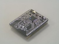
First picture shows a novel single-chip USB audio receiver & system control prototype module. My brother developed the software for this marvel. It contains many innovations, USB, CPU, and DAC timing signals are all derived from a single local masterclock (single time domain operation). Time domain dithering is applied, it has similar effect on sound like dithering applied after reducing resolution (CD recording).
So we end up with higher perceived resolution and there is no longer the need for sample rates above 96 KHz. This module talks multi-stream so we could finally dump the very problematic I2S interface and the required I2S to multi-stream decoder. The major problems with I2S are the high interference energy levels (symmetrical square waves with form factor 1) and spectrum (dominating odd harmonics & inter-modulation with every clock or data signal within in a radius of a few meters).
With the multi-stream interface we have very flexible data transfer and timing and the freedom to shape the digital audio interface spectrum any way we like. We now use very narrow pulses for both data and timing signals and spread spectrum timing.
The bit-perfect test is included of course and this chip also controls LED indicators, volume control relays and other I/O functions. This way we no longer need multiple processors in our application either.
The module contains an isolated USB bus voltage detection, USB EMI filtering and transient supressor chip, ultra low noise 3V3 voltage regulator and the 12 MHz masterclock. It supports almost any USB audio source (UAC1) without the need for drivers. The CPU load on the host CPU is as low as it gets, and data rate and related interference are low as a result of the novel tracking synchronization applied here. Because we only need UAC1 we can use the Adum4160 isolator to fix the ground loop issue.
We plan to use this module with different software for a TDA1541A DIY project using the TDA1541A simultaneous interface.
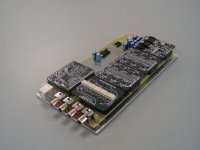
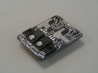
Next picture shows one of the Mosaic 25 D/A mono converter modules. The resistor matrix is in the center, the resistors are driven by fast CMOS logic that offers full 5.65Vpp (2Vrms) output. This DAC has to be driven in a very speciffic way and this is handled by the USB audio receiver module. The output impedance equals 750 Ohms.
Resistive level translators enable interfacing to 3V3 drive signals from the USB audio receiver module. The mono converters are powered by discrete +/-2V8 quatrode tracking regulators (DC-offset in the uV range).
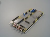
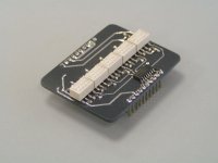
Next picture shows the stereo relay volume control module. We have 5 relays that offer 32 steps of -2dB attenuation. Relay driver (ULN2004) is used for buffering the USB audio receiver I/O lines. The resistors are thin film low noise precision resistors that also provide excellent tracking between both L and R channels. The signal part is very short and compact (low stray inductance and capacitance). The modular approach enables easy swapping of the modules for example when higher or lower impedance is required, this depends on the attached load and required output voltage.
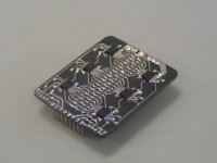
The next picture shows the quatrode tracking regulator module that provides -5V for the resistive level translators and +/-2V8 for the D/A converters. It contains two capacitance multipliers for reducing input voltage ripple, two pre (bulk) regulators for stabilization, current limiting and thermal protection and two quatrode voltage regulators. The positive 2V8 is fixed, the negative -2V8 tracks the positive supply by means of a slow DC-servo (0.1 Hz).
So now we have all the ingredients we need a mainboard that provides the interconnections, sockets, LEDs, and some extra circuits.
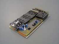
Next pictures show the completed Mosaic UV prototype, this is the new version that was just completed yesterday. We have two fixed and two variable RCA outputs, I selected RCA sockets that offer low Eddy current losses (point contacts and low mass ground sleeve). These sockets are individually screened for lowest possible hum. External inputs were removed as these cause unacceptable degrading as extra relay contacts need to be added to the signal path.
There is a push button for indicator LED on/off function and firmware uptates, and a large and rigid USB-B socket.
At the front we have 4 yellow LED indicators for sample rate, followed by USB connection (orange), USB streaming (orange), host muting (red), and bit-perfect test (green). In the center we have the IR remote control receiver and on the right we have 8 orange volume control indicator LEDs. If one wants to switch-off the LEDs after changing a function, this can be achieved with the push button at the rear. The selection will be stored in flash memory so you don’t need to re-program it every time you power up.
The mainboard requires +/-9 … 12V (unregulated) voltage source. I will integrate a mains power supply with additional CLC filtering in this novel Mosaic UV DAC.
Volume can be controlled by the IR remote control or at the host (host controls the relays in the Mosaic UV through the USB interface).
This is as simple, clean and straight forward as we could make it.
I like the built in volume control to eliminate need for a preamp. Can we see the included remote control for the mosaic uv?
The IR remote control is only 8mm thick and contains a rechargeable (USB socket) Lithium polymer battery.
It has been quiet for a while and that means more new developments.
Attached pictures show what we have been doing in the past months.
First picture shows a novel single-chip USB audio receiver & system control prototype module. My brother developed the software for this marvel. It contains many innovations, USB, CPU, and DAC timing signals are all derived from a single local masterclock (single time domain operation). Time domain dithering is applied, it has similar effect on sound like dithering applied after reducing resolution (CD recording).
So we end up with higher perceived resolution and there is no longer the need for sample rates above 96 KHz. This module talks multi-stream so we could finally dump the very problematic I2S interface and the required I2S to multi-stream decoder. The major problems with I2S are the high interference energy levels (symmetrical square waves with form factor 1) and spectrum (dominating odd harmonics & inter-modulation with every clock or data signal within in a radius of a few meters).
With the multi-stream interface we have very flexible data transfer and timing and the freedom to shape the digital audio interface spectrum any way we like. We now use very narrow pulses for both data and timing signals and spread spectrum timing.
The bit-perfect test is included of course and this chip also controls LED indicators, volume control relays and other I/O functions. This way we no longer need multiple processors in our application either.
The module contains an isolated USB bus voltage detection, USB EMI filtering and transient supressor chip, ultra low noise 3V3 voltage regulator and the 12 MHz masterclock. It supports almost any USB audio source (UAC1) without the need for drivers. The CPU load on the host CPU is as low as it gets, and data rate and related interference are low as a result of the novel tracking synchronization applied here. Because we only need UAC1 we can use the Adum4160 isolator to fix the ground loop issue.
We plan to use this module with different software for a TDA1541A DIY project using the TDA1541A simultaneous interface.
Next picture shows one of the Mosaic 25 D/A mono converter modules. The resistor matrix is in the center, the resistors are driven by fast CMOS logic that offers full 5.65Vpp (2Vrms) output. This DAC has to be driven in a very speciffic way and this is handled by the USB audio receiver module. The output impedance equals 750 Ohms.
Resistive level translators enable interfacing to 3V3 drive signals from the USB audio receiver module. The mono converters are powered by discrete +/-2V8 quatrode tracking regulators (DC-offset in the uV range).
Next picture shows the stereo relay volume control module. We have 5 relays that offer 32 steps of -2dB attenuation. Relay driver (ULN2004) is used for buffering the USB audio receiver I/O lines. The resistors are thin film low noise precision resistors that also provide excellent tracking between both L and R channels. The signal part is very short and compact (low stray inductance and capacitance). The modular approach enables easy swapping of the modules for example when higher or lower impedance is required, this depends on the attached load and required output voltage.
The next picture shows the quatrode tracking regulator module that provides -5V for the resistive level translators and +/-2V8 for the D/A converters. It contains two capacitance multipliers for reducing input voltage ripple, two pre (bulk) regulators for stabilization, current limiting and thermal protection and two quatrode voltage regulators. The positive 2V8 is fixed, the negative -2V8 tracks the positive supply by means of a slow DC-servo (0.1 Hz).
So now we have all the ingredients we need a mainboard that provides the interconnections, sockets, LEDs, and some extra circuits.
Next pictures show the completed Mosaic UV prototype, this is the new version that was just completed yesterday. We have two fixed and two variable RCA outputs, I selected RCA sockets that offer low Eddy current losses (point contacts and low mass ground sleeve). These sockets are individually screened for lowest possible hum. External inputs were removed as these cause unacceptable degrading as extra relay contacts need to be added to the signal path.
There is a push button for indicator LED on/off function and firmware uptates, and a large and rigid USB-B socket.
At the front we have 4 yellow LED indicators for sample rate, followed by USB connection (orange), USB streaming (orange), host muting (red), and bit-perfect test (green). In the center we have the IR remote control receiver and on the right we have 8 orange volume control indicator LEDs. If one wants to switch-off the LEDs after changing a function, this can be achieved with the push button at the rear. The selection will be stored in flash memory so you don’t need to re-program it every time you power up.
The mainboard requires +/-9 … 12V (unregulated) voltage source. I will integrate a mains power supply with additional CLC filtering in this novel Mosaic UV DAC.
Volume can be controlled by the IR remote control or at the host (host controls the relays in the Mosaic UV through the USB interface).
This is as simple, clean and straight forward as we could make it.
Attachments
the mosaic dac module has been developed late 2014. since then, the thing that keeps changing is the input/transport section. the DAC module is the same if Im not mistaken.You Guys are laughable, every month a new design
The website exhibits quite a few products - are any of them in production or are they made to special order only, and what are the prices like?
The E35 price for a basic 1541A dac chip, and some jfets on their surplus stock page, seems to indicate pretty high prices - maybe they're special?
The E35 price for a basic 1541A dac chip, and some jfets on their surplus stock page, seems to indicate pretty high prices - maybe they're special?
From the schematics I have seen recently, especially considering power supply (and not only this) - J.Browns design is head and shoulders above what is currently available in DIY 1541A form. And I can say that a few people who 'know' but remain either silent or impartial due to their own commercial interests (think HK and the EU) agree.
Wise man says, cheaper to buy it once and get it 'right'... and you know the rest.
LH/S
Wise man says, cheaper to buy it once and get it 'right'... and you know the rest.
LH/S
Last edited:
You Guys are laughable, every month a new design
this is the one and only formula for progress...and while EC has the inspiration for new inovations, we as "diy-ers" benefit also from his new concepts...think about how many designs and diagrams he shared with us all along this wonderful thread
Hi youknowyou,
Sorry for the late reply, too busy as usual.
There are plans to include a buffered (single-ended buffer) headphone output on the Mosaic DAC.
In order to disconnect it completely from the DAC section when not used, the headphone buffer has separate inputs that need to be connected to the variable DAC outputs.
I added a rough sketch that shows how this novel DAC may look like.
Sorry for the late reply, too busy as usual.
John, is there still the plan for a headphone amp/dac unit with the new (usb) mosaicUV?
There are plans to include a buffered (single-ended buffer) headphone output on the Mosaic DAC.
In order to disconnect it completely from the DAC section when not used, the headphone buffer has separate inputs that need to be connected to the variable DAC outputs.
I added a rough sketch that shows how this novel DAC may look like.
Attachments

Hi all, what do you think are these fake or real :
R1 is -lower- grading than plain A:
Philips - datasheet pdf
Check page 7
TDA1541A/N2 (plain A) bit 1-16 Edl < 1 LSB
TDA1541A/N2/R1 (R1 version) bit1-16 Edl < 2SLB
TDA1541A/N2/S1 (S1, single crown version) bit 1-7 Edl < 0.5 LSB, bit 8-15 Edl < 1 LSB
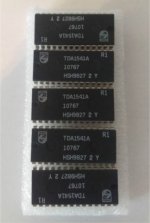
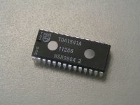
All original Philips chips I own have a white line left of the logo or a small vertical text “Taiwan”. I personally would be suspicious, especially when buying TDA1541A chips on ebay that are located in China.
The production year also has impact on bit accuracy and sound quality. It is logical that modern semiconductor production lines offer tighter tolerances compared to older production lines. But bit errors also translate to a specific distortion spectrum. So chips with similar bit errors, say 1 LSB can sound quite different because the distortion spectrum is different.
I bought a large -batch- of TDA1541A, 1998 chips from Taiwan production years ago that were intended for my DI-8 projects that contained 8 of these chips. We are selling these right now until stock is exhausted.
I added a close up of this chip. I have been using some chips from this batch in my TDA1541A projects for years because of the clean and refined sound. Only the TDA1541A-S2 1997 Taiwan production sounds better, but these are quite rare and come with a hefty price tag.
Anyway, here is the thread:
http://www.diyaudio.com/forums/swap-meet/298172-tda1541a-taiwan-sale.html#post4860505
Attachments
Hey guys, some time ago I finished (kinda) building my TDA1541 DAC. At first I tried NOS mode and I was amazed. Amazed how people can listen to it like this, I mean, it's so distorted..
Later I used SAA7220 and it's much better, music sounds like music..
Can anybody explain to me that phenomena? I suggest listening to "DM waiting for the night" , compare NOS and dunno, sound from a smartphone?
I'm not saying that it just sounds bad, I'm saying it's un-listenable, music is completely destroyed (on higher frequency I mean, I gotta say, bass is good)
I wish I could compare my build with others, maybe I got something wrong?
Later I used SAA7220 and it's much better, music sounds like music..
Can anybody explain to me that phenomena? I suggest listening to "DM waiting for the night" , compare NOS and dunno, sound from a smartphone?
I'm not saying that it just sounds bad, I'm saying it's un-listenable
, music is completely destroyed (on higher frequency I mean, I gotta say, bass is good) I wish I could compare my build with others, maybe I got something wrong?
Hey guys, some time ago I finished (kinda) building my TDA1541 DAC. At first I tried NOS mode and I was amazed. Amazed how people can listen to it like this, I mean, it's so distorted..
Later I used SAA7220 and it's much better, music sounds like music..
Can anybody explain to me that phenomena? I suggest listening to "DM waiting for the night" , compare NOS and dunno, sound from a smartphone?
I'm not saying that it just sounds bad, I'm saying it's un-listenable , music is completely destroyed (on higher frequency I mean, I gotta say, bass is good)
I wish I could compare my build with others, maybe I got something wrong?
I personally never heard a SAA7220 - TDA1541A combo producing music like vinyl and tape do.
There isn’t just one type of NOS DAC and like with OS DACs there are many factors that can lead to distorted sound. Think of jitter spectrum, I/V converter properties, power supply, DEM circuit, digital interface, analogue filter properties (if an analogue filter is used), TIM distortion in the connected (pre) amplifier.
The SAA7220 produces a lot of noise and jitter, this can mask distortion that the NOS DAC would let through. Most modern recordings are heavily compressed in order to make these sound as loud as possible, this can also be the reason that specific recordings sound bad on a some NOS DACs.
There are a number of commercial NOS DACs, or DACs that can be configured to operate in NOS that are highly regarded like Zanden and AMR-CD77 (filter setting 1 & 2) that are based on the TDA1541A (S2), Audio Note also offers some NOS DACs that are based on the AD1865.
I also demonstrated (TDA1541A) based NOS DACs at an audio show in Belgium and to a number of audio clubs, nobody complained about the type of distortion you describe.
It is not easy to get NOS working as planned, I spent over a decade to get optimal performance.
I am well aware that digital brickwall filters offer the best theoretical solution. But so far I haven’t heard any OS DAC that manages to produce music like vinyl and tape do. I listened to a number of SABRE DAC applications and state of the art OS DACs, despite on-chip digital filters and superior specs, there is no music.
I assume that the modern OS DAC chips have quite accurate on-chip digital filters, so there must be another reason why these theoretically correct DACs fail to produce music.
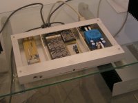
I designed and built many prototypes before we (my brother and I) arrived at the final Mosaic UV DAC design. This DAC produces music like vinyl and tape do.
Attached picture shows the current state of the final Mosaic DAC project, the housing is almost completed. This is not just another DAC, it is based on a novel type of USB audio receiver and the I2S interface is no longer used. This DAC runs on a multi-stream digital interface that produces only a fraction of the interference power levels produced by I2S.
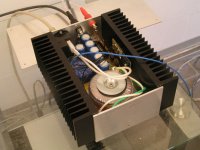
I use 10W single-ended lateral MOSFET monoblocks (second picture). These amps do not produce crossover distortion like push-pull amps do. There are no peak currents drawn from the mains, the monoblocks consume a steady 60 watts. I should have switched to single ended amps long time ago, but better late than never.
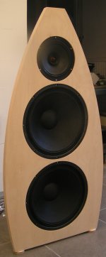
Then I designed some open baffle speakers to get rid of the coloured "box" sound and related issues with damping materials. Last but not least I use a point source here, so approx. 180Hz ... 25KHz are produced by one single speaker (third picture).
Attachments
- Home
- Source & Line
- Digital Line Level
- Building the ultimate NOS DAC using TDA1541A