Try a Dx Super A, or try TGM8 from Gareth Ingram (Bigun)
as Dx Super A can put out 80 watts RMS and TGM8 can put out 150 watts RMS...if your demand is power it is better to go to other designs.
Forum is plenty of nice designs that gonna provide you the power you need...this one was not designed for power...it was created under different philosophy, to work with highly efficient small speakers, some bookshelf units and dedicated to old people that loves such kind of old style sound.
People from UK, the old folks...more than 50 years old will appreciate the kind of sonics that will remind them their youth.
regards,
Carlos
Last edited:
P= I^2R = V^2/R = IR
If you have 1.2A and 8r0 then maximum P = 1.2^2 * 8 / 2 = 5.76W
You can't get 30W from a 1.2A supply.
When driving a reactive speaker load you will get less than 5.76W into 8ohms.
Hello AndrewT
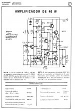
How it is possible if i have 60v dc and 1.2A (single)power supply for amplifier i will get only 5.76W into 8 ohm load ,I have Philips 40 watt amp it can produce 40 watt at 8 ohm load with same power supply.
i have attached schematic . If i am missing something please clarify .
Attachments
there is no substitute for a real live testing....
an 8 ohm dummy load, a signal generator and a scope....
paper computations are just that.....computations...")
ain't nothing like the real thing....
and why you may ask? it's because paper computations
do not take into account your actual psu, how big or how small is your traffo....
actual testing puts aside all doubts....
i know a lot of folks who are good at computations, but show them
a real amp and they get lost...
an 8 ohm dummy load, a signal generator and a scope....
paper computations are just that.....computations...
ain't nothing like the real thing....
and why you may ask? it's because paper computations
do not take into account your actual psu, how big or how small is your traffo....
actual testing puts aside all doubts....
i know a lot of folks who are good at computations, but show them
a real amp and they get lost...
Safety ground connected.
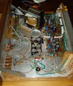
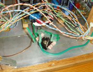
Hello again. My DX-Trust is still playing happy music, even if it is still not finished. The weakest link now seems to be the old cheap speakers. Maybe I need have a look at a speaker project one day soon.....
The safety ground is now connected, one wire to the transformer core, another to the heat sink. From the heat sink the ground wire continues to a ground lift circuit consisting of a bridge rectifier and two 27 ohm/3W resistors. The other end of the bridge/resistor combination is connected to the aluminium case lining and to the negative terminal of the power supply, which also serves as the ground star.
I believe that the amp is electrically as safe as can be with this setup, please see the attached photos.
Attachments
An externally hosted image should be here but it was not working when we last tested it.
Looking at this schematic, on the vbe multiplier we have a 0,2V (17.6-17.4V) drop on the trimmer+R group (680ohm+500ohm trimmer).
In my case the total resistance needed to set the bias properly is 680+70/80 ohm so a 220ohm trimmer would be also good but I can't find either 220 or 500 or 1K ohm trimmer...just 2k trimmer or bigger.
In that case 2k trimmer would be set "quasi-to-zero" to have only 80-90ohm resistance.
do you think that it could burn out?
Current on that group should be I=V/R, I=0.2V/680+1900= 0.2/2580=0.077mW. trimmer is suited for 250mW (at maximum resistance, I think).
is it right?
after few days listening to this little amp, I can only confirm how good it sounds.
Sounds it's very pleasant, round and middle are fantastic.
Pity for its low power, it can't moves my woofers as well as they should be.
Anyone can suggest any mods to improve it?
Bias is set to 15mA and also after 1 hour sounding quite loud, devices are COLD. no heat from this amp, maybe they can run also with very small sink (I tried 3cmx4cm sink and it was also good).
regards
Does anybody know why this amp onscillate when the zobel in the amp is 2r2+22nf?
I used that value cause it was in the pcb i used, but in the schematics it was 220nf.
When using 22nf bias current starts to rise from10ma to 300-400ma. With 220nf all is right.
I'm just curious about that.
Regards
I used that value cause it was in the pcb i used, but in the schematics it was 220nf.
When using 22nf bias current starts to rise from10ma to 300-400ma. With 220nf all is right.
I'm just curious about that.
Regards
The Zobel is an RC filter. It therefore has a time constant according to the RC product and this also influences frequency compensation and hence the stability of the amplifier.
If the Miller compensation cap, C6, for example, is too small for the particular components you have used, the amplifier will become unstable and oscillate. Using larger capacitance in the output Zobel network has probably helped there that but not the best way.
Ball-park values for Zobel networks are 100nF + 10R as shown on the schematic and yours were only 22nF and 2.2R. What did you expect? That is an unusually small Zobel by a factor of >10 and many amplifiers could have problems. However, frequency compensation should be established at the compensation cap C6, as combined with a BD139 for Q2 - not necessarily here at the output stage.
How did it happenl? In my experience, DIYs substitute some very low capacitance, high speed components for sluggish ones in the VAS and for other functions, in order to improve performance or just because that's what the other guy did. 'Seems like a good idea but you still need to know exactly how amplifiers work and what the phase margin and bandwidth conditions are when you start, in order to keep the amplifier stable. If you don't understand the factors of stability, but still change critical circuit values affecting frequency compensation, you will cause problems.
Good that you have solved yours but I would look at post #5 and other comments by DX to get a better idea of what you are doing.
I read all the thread many thanks
The zobel in the schematics is 2R2+220nf but in the pcb file it was 22nf, so I made the mistake.
I think 22nf causes an oscillation because with no speaker connected I can perfectly regulate bias; when conneting speaker the bias goes to 500ma heating devices.
Also the miller cap is 100pf, and I used that value.
Another question is about R10 (2K7, sensitivity adj??)...with recommended value I have a distorted sound. I have to use 1K instead to get right. This happened with all devices used...do you know why?
many thanksThe zobel in the schematics is 2R2+220nf but in the pcb file it was 22nf, so I made the mistake.
I think 22nf causes an oscillation because with no speaker connected I can perfectly regulate bias; when conneting speaker the bias goes to 500ma heating devices.
Also the miller cap is 100pf, and I used that value.
Another question is about R10 (2K7, sensitivity adj??)...with recommended value I have a distorted sound. I have to use 1K instead to get right. This happened with all devices used...do you know why?
The bias appears to be high because of the extra current drawn and dissipated in the circuit and speaker coil when oscillating. You can burn speakers and amplifiers that way.
I referred to the schematic in #6, There may be others in the thread that are different but I haven' t looked at them. R10+R9 is a voltage divider that as you suspect, controls the voltage swing of the VAS. If the sound is distorted with the values shown, does this occur with any input level, or just at high output level?
I referred to the schematic in #6, There may be others in the thread that are different but I haven' t looked at them. R10+R9 is a voltage divider that as you suspect, controls the voltage swing of the VAS. If the sound is distorted with the values shown, does this occur with any input level, or just at high output level?
I have only built two versions of the DX range of amplifiers.Does anybody know why this amp onscillate when the zobel in the amp is 2r2+22nf?
I used that value cause it was in the pcb i used, but in the schematics it was 220nf.
When using 22nf bias current starts to rise from10ma to 300-400ma. With 220nf all is right.
I'm just curious about that.
Regards
They lie on the shelf because I could not prevent the ringing and ocassional full oscillation with slightly reactive loads.
I have followed most of the DX range in their various Threads. I do not believe the Designer knows how to properly test and adjust an amplifier for unconditional stability.
And since I don't know either (I don't claim to be an amp designer) I cannot offer a known solution.
The bias appears to be high because of the extra current drawn and dissipated in the circuit and speaker coil when oscillating. You can burn speakers and amplifiers that way.
I referred to the schematic in #6, There may be others in the thread that are different but I haven' t looked at them. R10+R9 is a voltage divider that as you suspect, controls the voltage swing of the VAS. If the sound is distorted with the values shown, does this occur with any input level, or just at high output level?
this occur with any input level. I suspect it's a distortion caused by a not proper polarization with 2k7. Consider that I'm using BD139/16, BC556B and TIP35c /TIP36C.
but with 1k in that place I solve the problem, bias is stable, also VCC/2, sound is not distorted.
I've build many of this amplifier 'cause it sounds very very very good. It has output cap (no protection needed) and very low bias....if you need a few watts it's very good, I think better of any commercial kind to 1-2000 USD.
It has upgradable driving capability, I think, but with high efficiency speakers and right volume it can sound pleasant. This is, obviously, my opinion.
I don't sell it, but I can only recommend to try it. Sound is something special
- Status
- This old topic is closed. If you want to reopen this topic, contact a moderator using the "Report Post" button.
- Home
- Amplifiers
- Solid State
- Trust, the most delicious Dx Amplifier