Dont get too impressed by the graphs, they are smooth because i use 1/24 smoothing from the program. But if you look at the graphs bellow, wich are non smoothed now, you will see that if i increase the distance from the mic to ruban, the graph becomes pretty messi (exactly as it was before) as you can see bellow.
I made my meaurements after i spoked with a friend of mine wich is winding and refurbishing speakers, and he told me that if i dont have an anechoic chamber i should measure the rubans from very close distance (about 2cm from the bonding) because the mic is omnidirectionall and could pick up allot of reflections and ground noise.
After speaking to him i readed a tutorial on the web of how do i have to measure a speaker, to confirm this aspect, and what do you know, it seems that the mic was really picking up reflections and ground noise from my listening room as the distance from the membrane bonding increased.. Look bellow ,i posted the "classic" ruban measurements again with no smoothing and increased distance.
The thing is the ruba emits highs from more then only the center. so at a distance they all did there job in decreasing highs or increasing highs due to phase isues. when you get up close to one particular part that emits high frequencys this part will dominate or phase isues shift out of the pass band, hence a flater curve.
Ofcourse closer looks beter but allot of NULLS at that high frequency is not due to the room reflection if you ask me, usually the low end is affected allot by the room. not the Upper range. if i measure a ESL at 1 cm distance will be a complete different plot in the low end then at say 30 cm or 1 meter. in the end you wont be listening at 1 cm distance. also directivity factor is completly ignored when measuring that close. unless you got your head in a vise the curve can change dramaticly. as we seen in measurements of mine. slightly off axis Highs tend to increase and then fall off. on 0 degree there are dips caused by phasing i believe.
I guess that the magnets have the flux through the largest surface?
FEMM cannot simulate according to your layout as it would require 3D simulation, The drawing should be made as an inter section seen from the top (or bottom).
A glance at your drawing tells me that there are no magnetic circuit with gaps.
What are you trying to accomplish (I haven't read the whole thread)?
Anyway, I'll try to simulate it in a day or two.
(PM me if you want my attention, I'm not that active when it comes to DIY Audio right now. I've been too busy building on my big di-pool the last year or so)
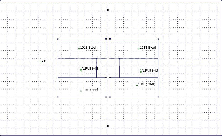
Sorry here it is. I have atached a top view and laterall view. I want to know if it will saturate with the magnets close at 6mm from the steel plates edges and 4mm gap as drawed in the pics bellow.
Now, as we speak, my magnets are at 1 cm dist fom the edge and 3 mm gap.
My magnets are N42, neodim, 40*20*10mm aranged as in the pic bellow.
Thanks
Sergiu
Attachments


Last edited:
The thing is the ruba emits highs from more then only the center. so at a distance they all did there job in decreasing highs or increasing highs due to phase isues. when you get up close to one particular part that emits high frequencys this part will dominate or phase isues shift out of the pass band, hence a flater curve.
Ofcourse closer looks beter but allot of NULLS at that high frequency is not due to the room reflection if you ask me, usually the low end is affected allot by the room. not the Upper range. if i measure a ESL at 1 cm distance will be a complete different plot in the low end then at say 30 cm or 1 meter. in the end you wont be listening at 1 cm distance. also directivity factor is completly ignored when measuring that close. unless you got your head in a vise the curve can change dramaticly. as we seen in measurements of mine. slightly off axis Highs tend to increase and then fall off. on 0 degree there are dips caused by phasing i believe.
I think you are completely right my friend. I did measure that close just to see ("dig ") the actual frecvency resp wich is comming out directly from the speaker without being altered or damped or whatever.
First i want to increase sensitivity and then redo another fresh set of membranes and see what happends from 1m when sesitivity is increased.
Cheers
Sergiu
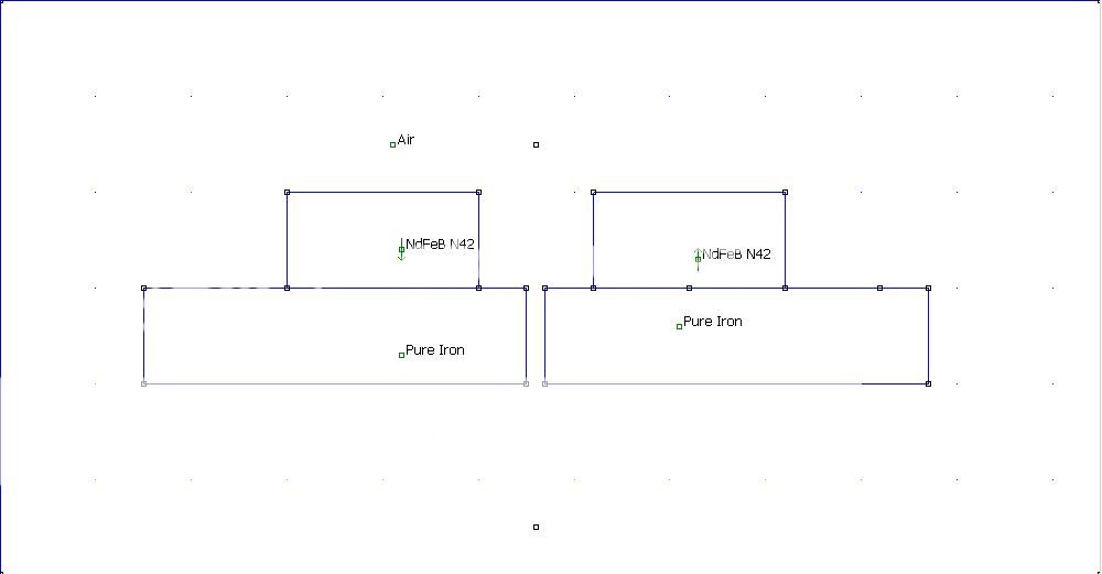

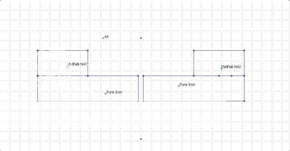
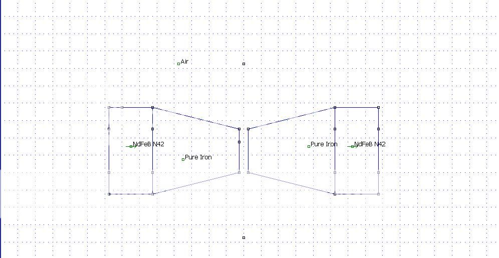

Sorry for the misunderstanding. I'll do a new simulation shortly.Nope, the motor looks more like the one from bellow. With a 4mm gap for the coil and the magnets at 6mm from the edge.
Can you change the plates material from pure iron to cold rolled steel?
Thanks
Sergiu
What type of cold rolled steel are you using?
These are the ones that FEMM has in its library:
An externally hosted image should be here but it was not working when we last tested it.
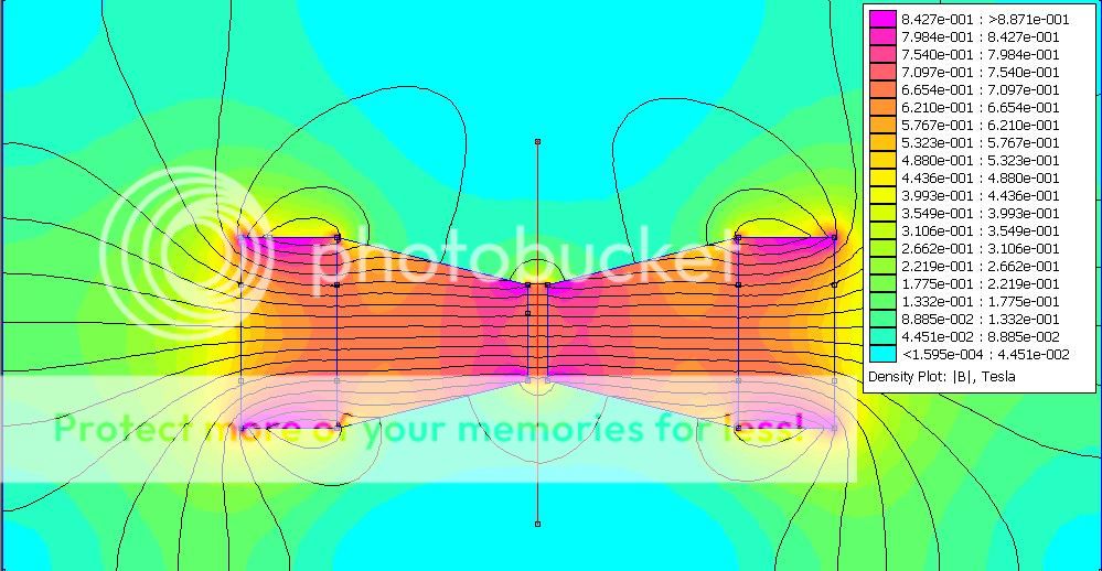
I have simulated with these before, the result doesn't change much from Pure Iron. Just how saturated the material can get really.
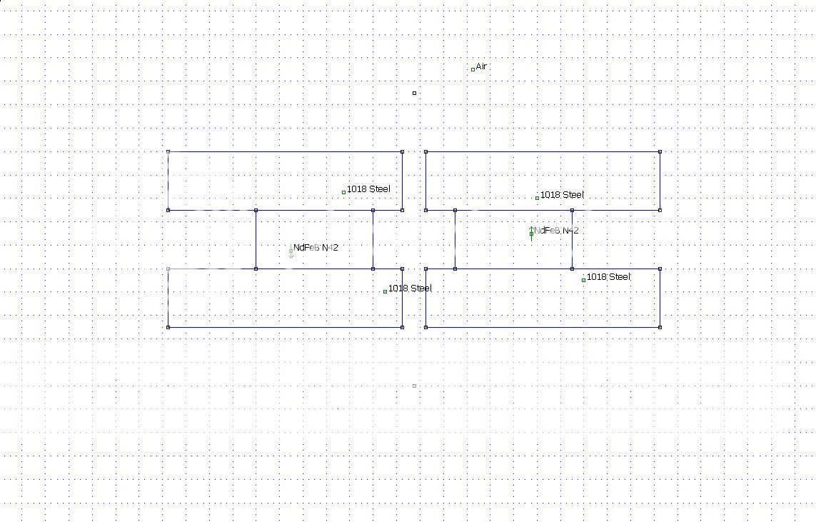
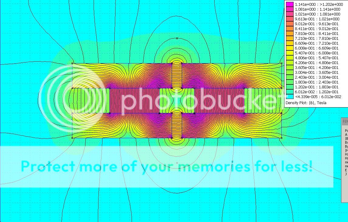
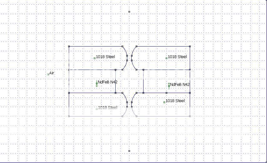
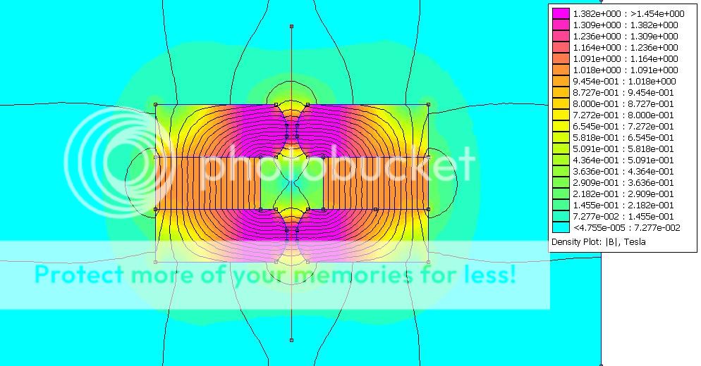
This is the same simulation as the last but with 1018 Steel instead:
An externally hosted image should be here but it was not working when we last tested it.
The steel is aisi 1017. But you can simulate it with 1018. No prob for me.
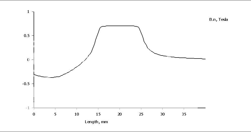
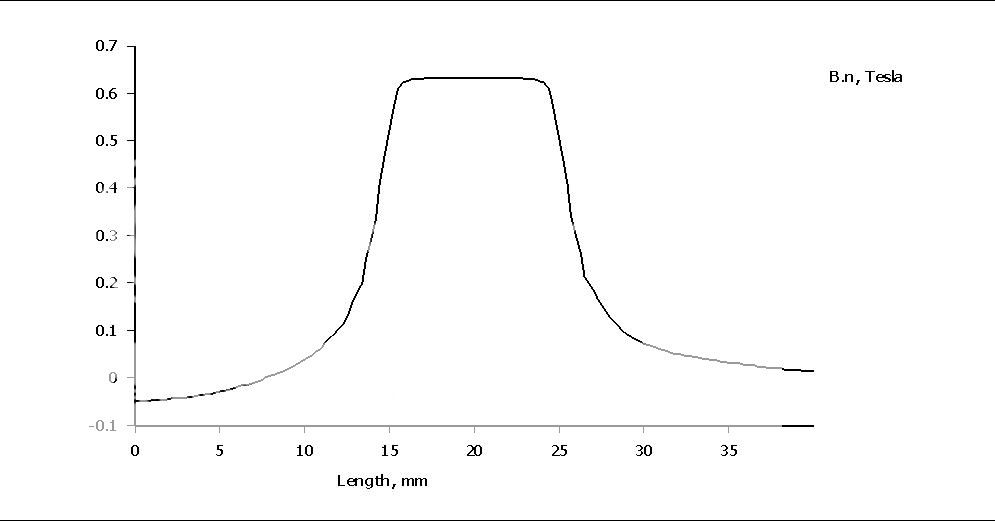
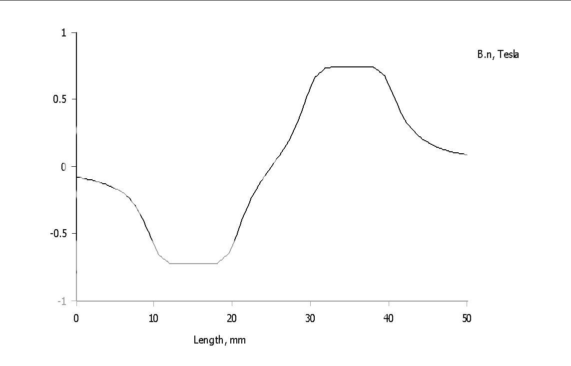
But i am a bit confused, i have only 0.7 T between 15mm and 30mm gap?? Is this an average or what? I think is very low.. isnt it suposed to be higher?
I just disassembled the rubans and preparing them for the milling machine.
Thanks
But i am a bit confused, i have only 0.7 T between 15mm and 30mm gap?? Is this an average or what? I think is very low.. isnt it suposed to be higher?
I just disassembled the rubans and preparing them for the milling machine.
Thanks
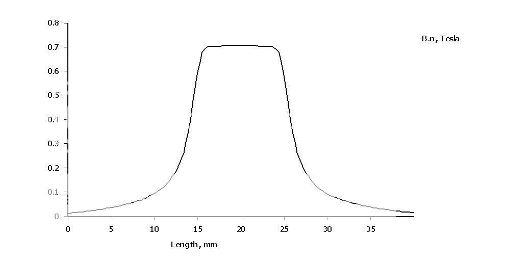
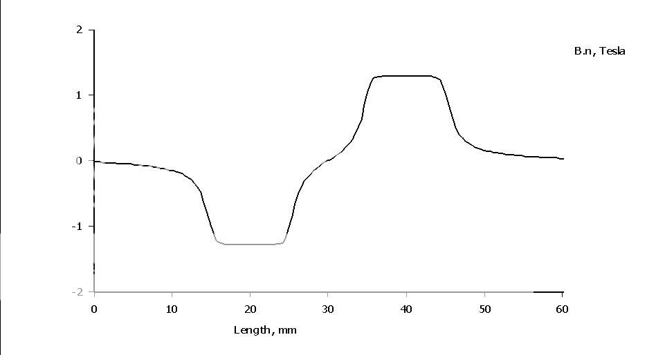
It is how the flux density varies along the vertical red line in gap.I meant the 0.7 T described by the curve from the graph is between the magnets and the 1T from the 2D graph is referring to the flux from between the plates?
0 mm is at the top and 40 at the bottom.
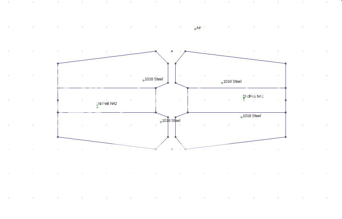
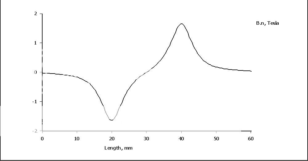
So, if i have the edges from the plates straight i have 0.7T , but if i have the edges rounded like in the pics bellow? Please have a look at the pic bellow because i couldnt draw them in paint..
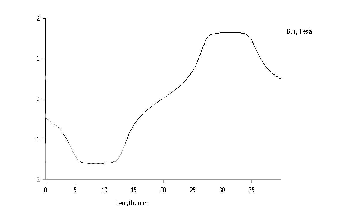
So it seems that i will get a maximum 1.1~1.2T at max if i have the plates edges smoothed out?
To me it looks like neither of the actual sellers of this speaker doesnt have more than 1.4~1.5 T with stronger n54, neodim 40*20*10....")
I disassembled the rubans yesterday and preparing them for milling today.
I remember very well that interesting structure but it has some problems, and one of them is that you need a CNC (wich is no prob for me) and a 520*50*20 mm aisi 1018 or 1017 steel bar to be prelucrated like that wich is a real problem for me because i allready waited 1 week for this aisi 1017 520*40*10 mm to come... Another aspect is that you have to orientate the magnets horizontally instead of vertically as me and Wrine and the official sellers of this speaker do, wich means double the magnets and this way the party starts to get expensive. N 42 magnets are expensive but accesible but n54 are almost triple the price...
It will remain a goal for me in the future as an upgrade (its good to know).
Thanks
Sergiu
So it seems that i will get a maximum 1.1~1.2T at max if i have the plates edges smoothed out?
To me it looks like neither of the actual sellers of this speaker doesnt have more than 1.4~1.5 T with stronger n54, neodim 40*20*10....
I disassembled the rubans yesterday and preparing them for milling today.
I remember very well that interesting structure but it has some problems, and one of them is that you need a CNC (wich is no prob for me) and a 520*50*20 mm aisi 1018 or 1017 steel bar to be prelucrated like that wich is a real problem for me because i allready waited 1 week for this aisi 1017 520*40*10 mm to come... Another aspect is that you have to orientate the magnets horizontally instead of vertically as me and Wrine and the official sellers of this speaker do, wich means double the magnets and this way the party starts to get expensive. N 42 magnets are expensive but accesible but n54 are almost triple the price...
It will remain a goal for me in the future as an upgrade (its good to know).
Thanks
Sergiu
Attachments


So, if i have the edges from the plates straight i have 0.7T , but if i have the edges rounded like in the pics bellow? Please have a look at the pic bellow because i couldnt draw them in paint..
So it seems that i will get a maximum 1.1~1.2T at max if i have the plates edges smoothed out?
But with rounded edges you will get a smaller region that is linear.
What is your desired height of the gap, that is, do you aim for an under hung motor or an over hung motor?
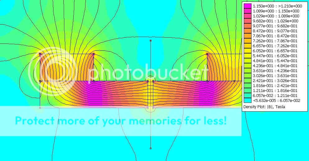
The problem with your suggestion is mainly that the flux takes other routes apart from the wanted ones. In this case on the other (outer) side from the magnets:
If you make the gap's height more focused, the flux density will be heigher but the height of the gap will be less:
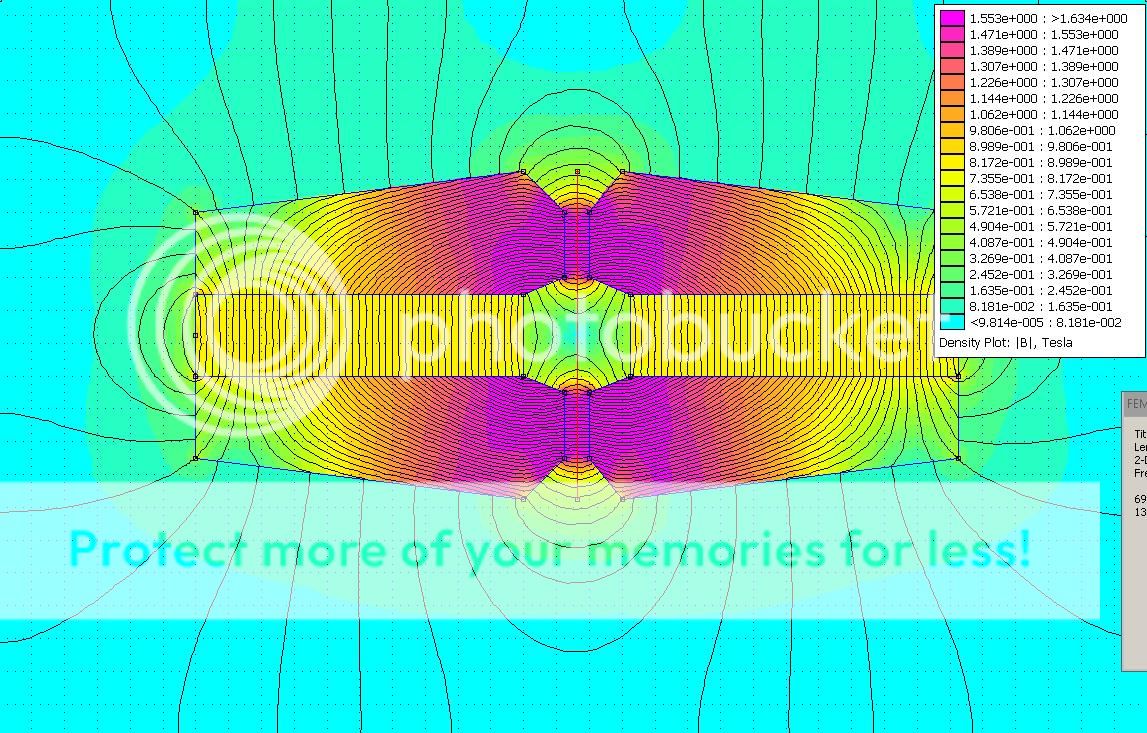
Here's a simpler motor:
With rounded gap, note that the height now is much smaller and not that linear:
The overhung metal mentioned somewhere in the begining of this thread is wasting flux, solhaga's design works around this all the metal is in contact and is thick enough in the places needed to not be saturated. And smaller then the overal thickness at the gap to focus the field nice design. 1,4 tesla
nice design. 1,4 teslaI don't know about the needed Xlinear for a Rubanoid. Perhaps a short gap is enough.
Perhaps it can be even shorter with a pointier pole piece or any other shape.
But then you're chasing tenths of T.
A problem with high flux densities in the gap is that the construction must be more rigid.
520 mm long pole pieces will for sure bend towards each other in the middle.
Perhaps it can be even shorter with a pointier pole piece or any other shape.
But then you're chasing tenths of T.
A problem with high flux densities in the gap is that the construction must be more rigid.
520 mm long pole pieces will for sure bend towards each other in the middle.
Thank you very much Solhaga. Your simulations explains allot of things for me. I forgot to tell you that this speaker sounded best in overhung mode (1.2cm coil shoulder vs 1 cm plate) and 1:1 coil width shoulder to plates width ratio (1cm coil shoulder vs 1cm plate). What has bigger field if flatter plate edges are used? What do you recomend?
I will post a drawing bellow from my phone with the dims for the modifications wich needs to be done at my actual plates. The zones that are shaded will be preciselly removed by my colleagues at the CNC at work. The modifs will begin this thursday 22.09.2016 and ends at the same day, so i want to ask you again for another simulation.
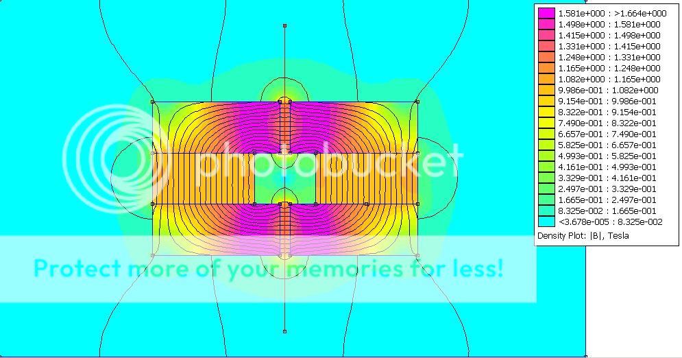
After the milling is done i will remain with the situation bellow (that i drew directly onto a simulation of yours). The question is : will those 2mm remained on the back of the magnets (outside the active area as i drew below) influence the flux density drastically and need to be removed or leave them as they are?
Knowing that aisi 1017 saturates at aprox 2.05T is it ok to increase the dist between the magnets and the plates edges (from the gap side) from 6 mm to 8 mm or leave it at 6 mm?
I ask you this because till thursday i can still modify my drawing.
Thanks in advance.
Cheers
Sergiu
I will post a drawing bellow from my phone with the dims for the modifications wich needs to be done at my actual plates. The zones that are shaded will be preciselly removed by my colleagues at the CNC at work. The modifs will begin this thursday 22.09.2016 and ends at the same day, so i want to ask you again for another simulation.
After the milling is done i will remain with the situation bellow (that i drew directly onto a simulation of yours). The question is : will those 2mm remained on the back of the magnets (outside the active area as i drew below) influence the flux density drastically and need to be removed or leave them as they are?
Knowing that aisi 1017 saturates at aprox 2.05T is it ok to increase the dist between the magnets and the plates edges (from the gap side) from 6 mm to 8 mm or leave it at 6 mm?
I ask you this because till thursday i can still modify my drawing.
Thanks in advance.
Cheers
Sergiu
Attachments

Here it is. This is the scetch that i drew for the guys. This will be for a single plate. The 13 pcs drilled holes will be filled by custom aisi 1017 rods (group of durity is Group 10.9 wich is the strongest) alternatelly so that they will not cause magnetic short circuit and they will keep the magnests still, instead of the 1cm square Al 52cm long pipes.
The 5 drilled holes will be filled by tensioning rods wich will have a strong suport as a reference to hold on and they will keep the steel plates tensioned so that they will not bend. I have readed on the net that aisi 1017 steel has more pure iron in it and less manganese and is less flexible compared to aisi 1018. So i have to keep this thing in mind and be very carefull.
Thanks
Attachments

I will look at this this evening.Thank you very much Solhaga. Your simulations explains allot of things for me. I forgot to tell you that this speaker sounded best in overhung mode (1.2cm coil shoulder vs 1 cm plate) and 1:1 coil width shoulder to plates width ratio (1cm coil shoulder vs 1cm plate). What has bigger field if flatter plate edges are used? What do you recomend?
I will post a drawing bellow from my phone with the dims for the modifications wich needs to be done at my actual plates. The zones that are shaded will be preciselly removed by my colleagues at the CNC at work. The modifs will begin this thursday 22.09.2016 and ends at the same day, so i want to ask you again for another simulation.
After the milling is done i will remain with the situation bellow (that i drew directly onto a simulation of yours). The question is : will those 2mm remained on the back of the magnets (outside the active area as i drew below) influence the flux density drastically and need to be removed or leave them as they are?
Knowing that aisi 1017 saturates at aprox 2.05T is it ok to increase the dist between the magnets and the plates edges (from the gap side) from 6 mm to 8 mm or leave it at 6 mm?
I ask you this because till thursday i can still modify my drawing.
Thanks in advance.
Cheers
Sergiu
Sorry, I don't understand where the magnets mounted.Here it is. This is the scetch that i drew for the guys. This will be for a single plate. The 13 pcs drilled holes will be filled by custom aisi 1017 rods (group of durity is Group 10.9 wich is the strongest) alternatelly so that they will not cause magnetic short circuit and they will keep the magnests still, instead of the 1cm square Al 52cm long pipes.
The 5 drilled holes will be filled by tensioning rods wich will have a strong suport as a reference to hold on and they will keep the steel plates tensioned so that they will not bend. I have readed on the net that aisi 1017 steel has more pure iron in it and less manganese and is less flexible compared to aisi 1018. So i have to keep this thing in mind and be very carefull.
Thanks
Could you make a simple "3D" sketch?
- Home
- Loudspeakers
- Planars & Exotics
- A DIY Ribbon Speaker of a different Kind