Hey everyone,
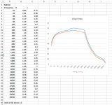
I had my Macintosh MX110 recapped a few months ago, and I have never been quite pleased with the sound. To get it to where it sounded ok I would have to crank up the bass and treble almost all the way, but that brought in a lot of noise. So today I did tried to test the frequency response with an old signal generator and two multimeters. I tried to use a dummy load (an 8ohm 100 whats resistor), but I couldn't get a decent response out of that, so I ended up not using a dummy load at all. I attached my results for the left and right channel. I knew the high end was bad but this is really really bad. The guy who recapped it, only does restorations, he doesn't do general work, his 30 day warranty is up. Should I bring it back to him, or just try a new place? What could even be causing this? Thanks for the input!
I had my Macintosh MX110 recapped a few months ago, and I have never been quite pleased with the sound. To get it to where it sounded ok I would have to crank up the bass and treble almost all the way, but that brought in a lot of noise. So today I did tried to test the frequency response with an old signal generator and two multimeters. I tried to use a dummy load (an 8ohm 100 whats resistor), but I couldn't get a decent response out of that, so I ended up not using a dummy load at all. I attached my results for the left and right channel. I knew the high end was bad but this is really really bad. The guy who recapped it, only does restorations, he doesn't do general work, his 30 day warranty is up. Should I bring it back to him, or just try a new place? What could even be causing this? Thanks for the input!
Attachments
Nice telephone you've got there. Could also be your multimeter though - what is its frequency range spec for AC? Ones suitable for 20 kHz and up tend to be >$100US.
Going by the small kink around 400-ish Hz, the neutral position for the bass control may be a bit above center.
I am not surprised you had no luck with the 8 ohm dummy load - this unit is a pretuner, and the output is tapped from a 40k volume pot, so output impedance would be well in the kOhms more often than not. Your voltage would be dropping right into the single-digit millivolts with the dummy load attached.
You may be better off running an RMAA loopback test over it via your computer's sound card - even your modest onboard audio should be able to record at up to 192 kHz fs if set up correctly, easily giving you 40+ kHz of bandwidth.
Should the drastic cut in highs response turn out to be real, further investigation would be needed. It could not be the result of replacing electrolytics alone. Does this unit still use paper caps or films already? Have any of those been replaced?
Thanks for your reply. My multimeters are both in good working order and both give the same results. When you ask for the frequency range for the AC I am not sure what your asking for, if you mean the preamp its 20 to 20k I believe.
Would not using a dummy load have effected my results? I would assume the meter as some resistance.
Not sure how to run the RMAA, any recommended free software?
All electrolytic and paper caps have been replaced, but I don't think it ever had paper caps.
Would not using a dummy load have effected my results? I would assume the meter as some resistance.
Not sure how to run the RMAA, any recommended free software?
All electrolytic and paper caps have been replaced, but I don't think it ever had paper caps.
Could also be your multimeter though - what is its frequency range spec for AC? Ones suitable for 20 kHz and up tend to be >$100US.
Oh I think I know what you mean now. My multimeter doesn't test frequency. I was testing for the change in volts. I would keep the voltage of the signal generator constant at 1.5 volts for each frequency input, and then measure the the voltage that came from the output. I used the difference from a reference voltage at 1000K for the DB graph. Let me know if there is something fundamentally wrong with that.
Loading a preamp with 8 Ohms is not correct, should be at least 10K Ohms or so. Also the frequency response of typical DMMs is not very good, looks like yours craps out at about 4K. Try measuring the output of the generator with your DMM and see how it compares with your other measurements. If it is your meter the results should be close.
Craig
Craig
Hi Craig,
Yeah, his meter has crapped out. The 8R dummy loads don'e help either.
Hi bodonnell,
What meters to buy? Higher model Fluke, Kiethley and Keysight. I don't trust most others. I used to calibrate meters full time.
-Chris
Yeah, his meter has crapped out. The 8R dummy loads don'e help either.
Hi bodonnell,
Most meters don't do that well even at 1 KHz, so you need to use either an AC meter or an old VTVM (yes, those work). Try a 10 Kohm load for starters. That would be the old standard load for signal out stages. Run your preamp out at about 316 mV (-10 dBv) and measure from there. If you want, you can run the output up to 1 Volt rms, or peak. Whichever makes you the most happy.Let me know if there is something fundamentally wrong with that.
What meters to buy? Higher model Fluke, Kiethley and Keysight. I don't trust most others. I used to calibrate meters full time.
-Chris
Dude, a meter is the wrong tool for measuring frequency response. You need a soundcard or interface hooked to a computer and do a loopback response. Soundcard out to preamp in, preamp out to soundcard in. Use REW for software. It will measure THD too. You can adjust the EQ controls and find out really fast what frequencies and Q's they affect.

REW - Room EQ Wizard Room Acoustics Software
Don't forget to just loop your soundcard/interface first and generate a calibration file that takes it's own rolloff out of the equation for the DUT.
REW - Room EQ Wizard Room Acoustics Software
Don't forget to just loop your soundcard/interface first and generate a calibration file that takes it's own rolloff out of the equation for the DUT.

That's fine by me, use what you want to. If you have a computer that has audio I/O on it, all you have to do is download some free software and you will gain resolution in your measurements, be able to test for THD and phase response as well and you will save yourself a couple of hours of time if you were to test things like THD numbers at various different output levels and what the EQ controls do.
If you use your computer soundcard and measure a power amplifier, and aren't quite familiar with what you are doing, you will soon have a computer with a blown soundcard recording section. They tend to die when they see much above 5V peak.
But otherwise, the soundcard and software will work fine, you just have to make sure not to overdrive the soundcard input. Maybe drive it via a 47k resistor.
If you are going to use a DVM to measure, though, make sure that it is a "true RMS" type and is rated to at least 20kHz. Not a lot of them are, you usually have to pay premium for that feature.
Use a voltage divider for power amps into a soundcard or interface. Either way though if you pay attention to the input level meter in REW you are not going to hurt anything. You can easily find the maximum input level on a soundcard by doing a loopback, running a sine in REW's generator and viewing the RTA display. Turn the THD calculator on and ease the level up and look for the point where THD starts climbing. That is max voltage point for your input.
Hi Shredhead,
Gee, my meters are good to 300 KHz, and I can put them into a nulled dB mode and sweep the frequency. That works for real quick tasks. I also have spectrum analyzers, but normally just use my meter (HP 34401)
I have used my sound card (bought for the purpose) and guess what I found out? You need to compensate any resistive divider used to keep the sound card in one piece. Compensation in this case is done with a meter for more accurate results. I don't use the sound card anymore because it needs a front end between it and the UUT. Setting levels with the sound card is more difficult too.
VTVMs work really well, they are fast and easy to use. You should try working with one, and they aren't stone age equipment. You can get very accurate results with a VTVM. Using a nice HP 652A audio generator will give you real sine waves to work with instead of the distorted signal generated by sweeping the signal. A function generator on triangle out will show the clipping point very accurately, or you can use a THD analyzer. That's a slow process.
Most often, the easy way out (sound card) has hidden gotchas. You have to understand your instruments and limitations or your test data could easily be invalid. After all, do you know what the distortion of your test card is configured as a test device? It isn't the nice low number on the box. You have to figure out what the limits are of your test signal is. You should measure that with a good THD meter. Level calibrations? Measure that too.
Don't dismiss options out of hand until you have experience with those techniques.
-Chris
Hi anatech. The OP doesn't have a meter that is accurate to 300k, I gave him an option that might not cost him any money. I don't understand what you mean by compensating the divider, can you show a schematic of what you had to do? I've never had any problems with damaging inputs, like I said if you pay attention to the input levels in the software, you won't damage anything.
I wouldn't say that I'm being dismissive to any methodology, everyone feel free to use whatever to measure things.
"VTVMs work really well, they are fast and easy to use. You should try working with one, and they aren't stone age equipment. You can get very accurate results with a VTVM. Using a nice HP 652A audio generator will give you real sine waves to work with instead of the distorted signal generated by sweeping the signal."
I have to say I disagree with this. If you took as many data points as the software does with a VTVM it certainly wouldn't be fast and good luck getting an accurate reading below 20Hz down to 2Hz with the needle dancing all over the place. Look, I've got respect for the old school but none of the major companies in the industry today are using a tube volt meter to measure the performance of their amps and preamps for the spec sheet and for good reason.
Also, why would you assume my card puts out distorted sine waves? Yes of course you measure the card in loop by itself to see what it's real numbers are, that's just obvious. Give me some credit here.
I ended up taking my preamp back in, apparently some tubes had crapped out and now it sounds fantastic! Night and day difference.
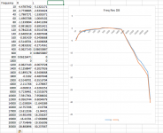
While I was waiting for my preamp to come back I tested my amp, this time with a dummy load (I did not use a dummy load for the preamp), I got a super flat response for the bass, but I got the same drop off on the high end. So apparently my meters aren't working for the high end. But I don't understand why, here is what I did:
Lets discuss the amp, since I had a proper 8 ohm dummy load on it. I hooked up a function generator and 1 meter to the amp input. I set the function generator so it was inputting 1.5 volts into the amp, and I adjusted the volume on the function generator so it maintained 1.5 volts for each frequency tested. From the output of the amp, I had a second meter and the dummy load. From the second meter I would record the voltage of the output, I then converted this all to DB using the voltage at 1k as my reference voltage.
So I understand that these meters might not work well for measuring frequencies, but is this the same for voltage? I would love to understand why the high frequencies dropped the voltage measurements.
Is there a better inexpensive tool I could use to measure this? I have a super old distortion analyzer. Would using that as a volt meter be better on the output side of the amp? Is there any thing wrong with using the multimeter on the input side to set the 1.5 volts.
- Status
- This old topic is closed. If you want to reopen this topic, contact a moderator using the "Report Post" button.
- Home
- Source & Line
- Analog Line Level
- Horrible Freq Resp from my MX110