But the derating is given for case temperature, not junction temperature.
se
Steve, I looked at some of those data sheets to find out at which point the 'case' was defined, but I cannot find it.
In my understanding, case temp is defined at the metal back that is in contact with the heatsink. You mentioned that it would be the plastic top of the case.
This is important for me so if you could point me to where this is mentioned, would be nice.
Jan
Attachments
Steve, I looked at some of those data sheets to find out at which point the 'case' was defined, but I cannot find it.
In my understanding, case temp is defined at the metal back that is in contact with the heatsink. You mentioned that it would be the plastic top of the case.
This is important for me so if you could point me to where this is mentioned, would be nice.
The BD139 doesn't have a metal back. It's fully enclosed in plastic.
se
Tjc has always been from the junction to the backside of the case wehre the metal contacts the heatsink.
The BD139 is fully enclosed in plastic, so there is no metallic contact with the heatsink.
se
The ON Semi datasheet shows a region of metal on the back for the BD139G, but perhaps you have a different case. See page 4 of the attached.The BD139 is fully enclosed in plastic, so there is no metallic contact with the heatsink.
se
Attachments
Just give it a big heatsink, problem solved....you are obsessing like Henrylrjr on another thread.
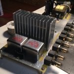
It already has a big heatsink (relative to the power it has to dissipate). It works just fine at typical room temperatures. I just want to verify that the case temperature will stay at or below 100°C in the event that some idiot leaves it turned on and leaves the house on some hot summer day with no cooling and the ambient temperature in the house hits 50°C.
I'm going to fire it up in a 50°C ambient temperature and would just like to monitor the case temperature to a reasonable degree of accuracy so that I can turn it off if the case temperature starts to go over 100°C. I only have two pre-production circuit boards and want to produce two pre-production amplifiers so I don't want to risk destroying one of the circuit boards if the output devices go over temp and fail.
You get it now?
se
Attachments
The ON Semi datasheet shows a region of metal on the back for the BD139G, but perhaps you have a different case. See page 4 of the attached.
The Fairchild devices I'm using are fully encased in plastic.
se
The ON Semi datasheet shows a region of metal on the back for the BD139G, but perhaps you have a different case. See page 4 of the attached.
Also, the Fairchild devices are sorted by hFE classification, the ON Semi devices are not which is why I'm using the Fairchild devices.
se
Put some 2 mm thick copper plate between transistors and heatsink. Transistor is dot source of heat, make it larger surface with high thermal capacity. For extended temperature range.
Those heatsink is perfect by dimension.
Are you talking about something permanent or just to facilitate temperature measurement?
se
But the derating is given for case temperature, not junction temperature.
se
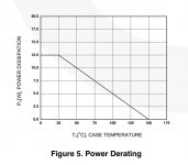
Look at the power derating graph -- at 0mW dissipation, max temp allowed is 150C. So that's the max junction temperature.
Edit: oops, I see Jacco got there before me...
Last edited:
Look at the power derating graph -- at 0mW dissipation, max temp allowed is 150C. So that's the max junction temperature.
Says "Case Temp" on the axis label....
I pulled up the datasheet on the fairchild bd139 from a googled alldata hit.
I see nothing to indicate that it's an isolated package. If it is, it impacts the derating curve.
The datasheet I found has Tc, or case temperature. For all practical purposes, that may as well be considered the heat-sink temperature, especially for the size you show and the thermal flux you'll be pushing. It should be within about 5 degrees of the backside of the case.
I am not confident a top of case measurement will be consistent with the datasheet. Nor, that it will represent the junction temp.
John
Ok, so take a few examples for testing.
Measure the case (plastic) carefully.
Save the measurements.
Now shave/abrade/grind the case to the minimum thickness possible both sides - mount with copper or aluminum on both sides of the device. Improved heat transfer will likely result. Of course your measurements are so you can more or less automate the process after determining the limits.
Did not see if these were flat pak or standard small signal devices with the round on one side. Making the round side flat will give another surface for heat transfer.
Or obviate the issue, use more devices or devices that can handle more powah??
Removing material from the backside is doable. From the front, it is not recommended not plausible, and of little worth.Ok, so take a few examples for testing.
Measure the case (plastic) carefully.
Save the measurements.
Now shave/abrade/grind the case to the minimum thickness possible both sides - mount with copper or aluminum on both sides of the device. Improved heat transfer will likely result. Of course your measurements are so you can more or less automate the process after determining the limits.
Did not see if these were flat pak or standard small signal devices with the round on one side. Making the round side flat will give another surface for heat transfer.
Or obviate the issue, use more devices or devices that can handle more powah??
I have lapped backsides to a mirror finish, both leaving the plating and removing to copper. (max, about 4000 grit) That certainly helps by removing the surface curvature caused by stamping of the leadframe. Still, thermal compound will be recommended. I would not recommend going finer than 1000 grit, as there are diminishing returns.
ON the top surface, the connections to emitter and base are typically wirebonds made of aluminum. The only thing that can be said about the height of the bonds is they have to be less than the top surface of the plastic. Other than that is truly a guess. One can lap several units until the wirebonds have been exposed, create a distribution, but then you still have to worry about manufacturing production lot variations. (Loop height may or may not be well controlled on the U/S bonder.)
As to the use of the topside surface as a heat transport surface, that is of little use. The backside copper will have a thermal conduction about two orders of magnitude higher than the top. If it is an isolated package, that will be about a factor of ten.
As an aside, in my search for the spec, I found a picture of a normal metal backed unit, and see that the encapsulation flashing goes over the copper a bit. That is absolutely HORRIBLE for thermal transport. If anybody is using standard non isolated, be very certain that the overmolding does not cause the metal to be raised from the heat sink surface, as silicone thermal compound is terrible for heat conduction.
John
Last edited:
Says "Case Temp" on the axis label....
Exactly.
The data sheet specifies a maximum junction temp of 150°C, but the derating curve is for case temp, and the ST data sheet give a delta T between junction and case of 10°C/W. In the current setup, each device is having to dissipate just under 4 watts, and from the derating curve, case temp can be just a bit over 100°C, but I'm setting the limit right at 100°C.
se
At zero dissipation how would case 5emp differ f4om junction?Says "Case Temp" on the axis label....
Btw, (I forget who) is right, a better thing to look at is Vbe vs temp at Ic....takes emitter resistance out of the problem. Though that makes the new problem of the IC changing the junction temp itself relative to the controlled temp. The IR sensor seems like the way to go. Or, hey, just use infinite heatsink, heatsink is free, right? Other than being maybe the most expensive part of a SE amp....
Or obviate the issue, use more devices or devices that can handle more powah??
I'm fairly confident I'll be ok as-is. I just want actual in situ confirmation while lowering the risk of damaging one of the circuit boards if I happen to be wrong and to do it with what I have available and without a lot of rigmarole.
se
- Status
- Not open for further replies.
- Home
- Member Areas
- The Lounge
- John Curl's Blowtorch preamplifier part II