Thanks George. I'm 69 and also live in Ct. I'm new to diy and electronics. All my stereo equipment was bought as completed components. The only diy I did was, not counting cables, outboard 3way passive crossovers I designed and built.
I new nothing about soldering, except for plumbing, so when I did the diy stuff I got caught up in the snake oil ads and bought a small spool of WBT 4% silver solder. I've only got about 1/2' left so need to buy some solder and felt the WBT, Cardas, and other "audoiphile" stuff was just hype. I was just trying to get the right stuff, most likely from Kester.
I new nothing about soldering, except for plumbing, so when I did the diy stuff I got caught up in the snake oil ads and bought a small spool of WBT 4% silver solder. I've only got about 1/2' left so need to buy some solder and felt the WBT, Cardas, and other "audoiphile" stuff was just hype. I was just trying to get the right stuff, most likely from Kester.
Thanks Tom. I'm reading so much trying to learn it and that make me question things. When a doc says something is not recommended for gold, and since I have so little knowledge, It drives me to ask questions.
The Wikipedia article you link to doesn't say "not recommended". It says at the first mention of gold in the article that if the amount of gold in the joint exceeds 4 %, the joint may become brittle. The way I read it is basically, "don't use common electronics solder for soldering your solid gold jewelry".
Poking around at connectors and such, you'll find the gold plating specified to be around 15-30 µm typically. The immersion gold (ENIG) used on PCBs is much thinner.
If a cone of solder soldered atop a layer of gold is 2 mm in diameter at the base and 2 mm tall, how thick does the gold have to be before it exceeds 4 % of the weight or volume of the total joint?
I do understand the learning experience and I do encourage you to ask questions. However, I also encourage you to try to answer the questions yourself as well, in particular as you have indicated some frustration with the conflicting information found on various online forums. I'm a big believer in learning through understanding rather than learning through memorization. That's why I try to ask for your thought process rather than just saying yes or no. I apologize if this goes against the grain.
Tom
I new nothing about soldering, except for plumbing, so when I did the diy stuff I got caught up in the snake oil ads and bought a small spool of WBT 4% silver solder. I've only got about 1/2' left so need to buy some solder and felt the WBT, Cardas, and other "audoiphile" stuff was just hype. I was just trying to get the right stuff, most likely from Kester.
About 2-3 weeks ago I spent most of a Saturday morning researching solder and typed up a thesis on the topic as a forum post to this thread. You can find it in Post #1636.
Tom
One solder accessory I have found very useful in limited situations is a flux pen. Basically a Sharpie type pen filled with liquid flux. I find it very helpful when dealing with high heat mass objects that are hard to heat up dry - things like some RCA's, binding posts, panel connectors, heat sink mounting tabs - anything bulky.
The pen allows a precision application of flux that will encourage melted solder to flow onto the object right where one wants. Heat transfer from the liquid (melted) solder is much more effective than a dry iron tip and one gets a better joint.
To me, effectively and fully heating both objects to be joined is priority one, regardless of chemical composition of the materials used.
Tom I believe you, and the few others who seem to be acknowledged as experts, that 63/37 and other lead/tin alloys won't be a problem with gold plated contact surfaces. I took what I read as truth and don't understand the detail.The Wikipedia article you link to doesn't say "not recommended". It says at the first mention of gold in the article that if the amount of gold in the joint exceeds 4 %, the joint may become brittle. The way I read it is basically, "don't use common electronics solder for soldering your solid gold jewelry".
Poking around at connectors and such, you'll find the gold plating specified to be around 15-30 µm typically. The immersion gold (ENIG) used on PCBs is much thinner.
If a cone of solder soldered atop a layer of gold is 2 mm in diameter at the base and 2 mm tall, how thick does the gold have to be before it exceeds 4 % of the weight or volume of the total joint?
I do understand the learning experience and I do encourage you to ask questions. However, I also encourage you to try to answer the questions yourself as well, in particular as you have indicated some frustration with the conflicting information found on various online forums. I'm a big believer in learning through understanding rather than learning through memorization. That's why I try to ask for your thought process rather than just saying yes or no. I apologize if this goes against the grain.
Tom
I guess the famous quote "a little knowledge is a dangerous thing" is a good example of my questions. The following is what made me ask the question.
This is the link https://en.wikipedia.org/wiki/Solder
In the section labeled Solder Alloys the following is included for Sn63Pb37
Sn63Pb37
Rapidly dissolves gold and silver, not recommended for those.[20].
The same statement is used for a number of other alloys.
Live and learn. Guess I'll cut back on my reading, do searches for my questions, and when I find posts that are from a recognized source, follow what the acknowledged experts say. I'm not looking to become an EE or an expert in electronics. Just want to put together an amp in the best way possible.
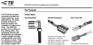
On a different topic; I bought the Molex crimper and tried it with some TE Connectivity Ultra-Faston Quick disconnects I happen to have. It didn't work.
I found the anvils of the, outrageously expensive, TE crimper and the TE connectors to be geometrically different than Molex stuff. Again I was fooled, or mis-led by reading and not understanding the details. I thought most things electrical were standardized. Foolish me. I've started contacting manufacturers to ask questions prior to purchasing anything..well not rubber bands.
Thanks
This is the link https://en.wikipedia.org/wiki/Solder
In the section labeled Solder Alloys the following is included for Sn63Pb37
Sn63Pb37
Rapidly dissolves gold and silver, not recommended for those.[20].
The same statement is used for a number of other alloys.
In the same article: "Tin-based solders readily dissolve gold, forming brittle intermetallics; for Sn-Pb alloys the critical concentration of gold to embrittle the joint is about 4%." (emphasis mine).
On a different topic; I bought the Molex crimper and tried it with some TE Connectivity Ultra-Faston Quick disconnects I happen to have. It didn't work.
Sorry it didn't work for you. I've had no trouble with the crimp terminals I pick up at the auto parts store. I believe they're Dorman brand.
Are you using the non-isolated kind (see attached)?
Tom
Attachments
I found Dorman stuff on the web. It seemed as good as any brand and car parts stores carried it. I went to two stores near me and they only had dormans for .250 wide X .02 thick terminals. I need .187 wide X .032 thick so got the TE Ultra-fastons. They are fully insulated as were the Dormans but the geometry was quite different. The dormans are much more like the Molex. Bottom line, I ordered some Molex and all should be fine.
Regarding the gold, is the idea is for the flux to remove the gold plating to avoid embrittlement. Since the plating is only microns thick it must be way less than 4% and easily dissolved away. Am I understanding this correctly?
Regarding the gold, is the idea is for the flux to remove the gold plating to avoid embrittlement. Since the plating is only microns thick it must be way less than 4% and easily dissolved away. Am I understanding this correctly?
The flux has absolutely no effect on the gold. The boiling flux cleans contaminants on the surfaces to be soldered.
It's the solder that dissolves the copper/silver/gold.
If you use enough solder while forming the joint, there is a very good chance that all the gold under the joint area is disolved into the soldering pool and is well below embrittlement concentrations at the interface.
One could try pre-soldering gold plated pads and solder wicking them almost clean before soldeing on your components. But I have never seen such a suggestion so I have never gone that far.
The flux has absolutely no effect on the gold. The boiling flux cleans contaminants on the surfaces to be soldered.
It's the solder that dissolves the copper/silver/gold.
If you use enough solder while forming the joint, there is a very good chance that all the gold under the joint area is disolved into the soldering pool and is well below embrittlement concentrations at the interface.
One could try pre-soldering gold plated pads and solder wicking them almost clean before soldeing on your components. But I have never seen such a suggestion so I have never gone that far.
Well said. Thank you.
While I do find the discussion about the metallurgy of solder and soldered connections fascinating, we're straying quite a bit off topic here and have started to beat the stain where the dead horse used to be on this issue. I suggest that those who are interested in this topic start a thread in the Equipment & Tools forum. I will be happy to participate there to the extent my time allows.
The Modulus-86 and all other product I offer is designed to be built using parts that are commonly available and in current production. The MOD86 is to be assembled using commonly available solder, wire, connectors, etc. The components should be used as produced by the manufacturers.
There is no need for horse hair cable ties, myrtle wood cable stands, or other fairy dust voodoo. Just attach a reasonably sized heat sink and connect the bits using commonly available parts according to the design doc and you will be successful.
I suggest using microphone cable from the input XLR to the MOD86 board. I suggest using wire in the AWG12 - AWG16 range for the supply connections and AWG12 - AWG14 for the output.
The Modulus-86 is not sensitive to power supply variation, hence, a smaller gauge wire is fine here. Any wire on the output adds directly to the output impedance, so a larger gauge wire is warranted here. The terminal blocks for the power supply and output accept wire up to AWG10 (5 mm^2) in size.
I need .187 wide X .032 thick so got the TE Ultra-fastons.
The 3/16" size is one of the many reasons I hate QC terminals with a passion. The SpeakON connectors I used had 3/16" terminals and I spent an ungodly amount of money on gold Audiophool spade connectors because that's what I could get at the auto parts supplier. There is a version of the SpeakON that uses 1/4" terminals, which are much more common. I suggest using that if you're going the SpeakON route.
Tom
Last edited:
Henry,
You're REALLY over-analyzing (as my wife would say) this soldering thing. The electronics industry has forever used tin/lead solder for its work, including gold-plated PCBs, gold-plated connectors, etc. My preference is for eutectic - 63/37 or similar proportions with a few % Silver. Eutectic tends to give better joints because it goes directly from liquid to solid without the intervening 'plastic' state. With 60/40 solder, if the joint is disturbed during the plastic state, you can end up with a cold joint.
The main impetus for adding silver to the mix was in the days of tube equipment (see classic Tektronix oscilloscopes, where components were soldered between ceramic barrier strips. The metal terminals were fused to the ceramic and contained a percentage of silver that was necessary to make the metal bond to the ceramic. If one did not use silver-bearing solder, eventually silver would leach from the terminal into the solder joint and this would cause the terminal to detach from the ceramic strip. If you want to see this sort of terminal strip, google "tektronix tube oscilloscope" and look at the images of the interiors of various scopes.
Back to solder: Given my preference (and recommendation to newbies) for eutectic solder, and given my general policy of 'prudent adoption' (i.e., if an audiophile tweak/fettish doesn't do harm and doesn't require significant expenditure of money), I use silver-bearing eutectic solder for my audio work, though I have non-silver-bearing as well as 60/40 that I also use. For PCB assembly, I prefer water soluble flux. It is very easy to clean in the kitchen sink with a toothbrush under running hot water, followed by a rinse of distilled or deionized (DI) water. The downside of water-soluble flux is that you MUST wash it off your board as it remains active even when cool.
If I need to buy (and I don't as I have about 4 pounds of it at the moment), I buy a name brand (Kester, Multicore, Reliacore) from Digikey. I wouldn't buy any no-name Chinese stuff off eBay -- had to use some belonging to a friend and it was junk.
If working with small SMT components, you'll want to get a very small-diameter solder.
BTW, there is nothing wrong with the WBT. I'm sure it's quite good, though significantly overpriced.
I've used lead-free solder and have not been impressed with it. It's difficult to work with and requires much more heat.
For PCB assembly, I prefer water soluble flux. It is very easy to clean in the kitchen sink with a toothbrush under running hot water, followed by a rinse of distilled or deionized (DI) water. The downside of water-soluble flux is that you MUST wash it off your board as it remains active even when cool.
I'd go with distilled water. DI water is rather reactive and doesn't actually stay DI for very long. If you happen to work in a research department or semiconductor plant with a supply of fresh DI water, that's another story. Then by all means use the company water.
")
I buy a name brand (Kester, Multicore, Reliacore) from Digikey. I wouldn't buy any no-name Chinese stuff off eBay -- had to use some belonging to a friend and it was junk.
Connectors (maybe) and mechanical parts may be OK to buy on ePay. Components, solder, etc. not so much.
If working with small SMT components, you'll want to get a very small-diameter solder.
My preference is 0.7 mm for leaded and 0.5 mm for SMD. The thinner solder makes it easier to get the right amount of solder into the joint.
Tom
I've found no problems with DI water, but if I didn't have it handy, I'd not go looking for it. It does a great job as the final rinse on the PCB. I'd surely not leave a PCB in DI water for a long time. Plain water for PCB cleaning may be OK if you have extremely good water, such as we had when living north of Seattle. Many parts of the country have high mineral content which leaves a deposit behind. Thus, the need to use distilled (or better) water for final cleaning/rinsing. The deposits can be somewhat minimized by blowing off the wet PCB with compressed air after cleaning.
Chinese: I was specifically talking about solder.
All my solder came in English dimensions. ;-)
Chinese: I was specifically talking about solder.
All my solder came in English dimensions. ;-)
I've found no problems with DI water, but if I didn't have it handy, I'd not go looking for it. It does a great job as the final rinse on the PCB. I'd surely not leave a PCB in DI water for a long time.
I think that's the key: If you just do a quick rinse in DI water and don't let the board soak for hours, you should be fine.
I usually use centrifugal force to get the water off. Then I get the rest with my heat gun or by letting the boards sit in a warm (80-100 ºC) oven for a few minutes.
Plain water for PCB cleaning may be OK if you have extremely good water, such as we had when living north of Seattle.
Yeah. The Seattle water is wonderfully soft. One could cry about the chlorine in it, but I doubt it's enough to cause trouble with the electronics.
The water in Calgary is harder (higher mineral content) but has much, much less chlorine in it. Tradeoffs, tradeoffs... In the end a gallon ... eh, I mean ... a 3.81 litre jug of distilled or DI water is available at the grocery store for not that much and is enough to rinse many, many boards.
Chinese: I was specifically talking about solder.
I know. I was just adding my public service announcement to your notion. I bought a resistor kit on ePay a few years back. 250 mW, metal film, 1 % tolerance. Or so they were marketed anyway. The tolerance is closer to 5 % and the paint job is so poor that the markings wear off when you handle the resistors by hand. They're OK for prototyping but for anything that I go public with I use resistors from a ±1 % kit I bought from Newark.
Tom
On a completely unrelated note: I am now using the MiniDSP 4x10 HD driving my LXmini speakers via my 4xMOD86 amp. That's a very nice combination! I use the 4 V setting (lowest gain, lowest noise) on the differential outputs of the MiniDSP. The source is the optical (TOSLINK) output on my 2010 MacBook Pro. Currently I use iTunes to play Apple Lossless files. I may try Audirvana Plus at some point, hoping to get a better remote control app. The FLAC support of Audirvana Plus would be welcome as well.
Tom
Tom
Hmm. Does 4V measure as lowest absolute noise or lowest relative noise? I'm guessing the former rather than the latter. Just curious.(lowest gain, lowest noise)
+1. I've usually some water bottles around where the chlorine's evaporated off anyhow as a courtesy to the houseplants (the idea came from a friend whose young son kept frogs). DI is cheap and handy for topping up one's car battery, though.Yeah. The Seattle water is wonderfully soft. One could cry about the chlorine in it, but I doubt it's enough to cause trouble with the electronics.
Last edited:
When learning to solder it's probably worth doing a little reading and maybe watching a few videos, but after that you have to do it. The only way to become a good solderer is practice, theoretical knowledge only gets you so far. The first boards will not be perfect, but with diligence will be perfectly functional.
Have fun!
Have fun!
Hmm. Does 4V measure as lowest absolute noise or lowest relative noise? I'm guessing the former rather than the latter. Just curious.
You can find the full data set here: MiniDSP 4x10 HD Performance Measurements.
4.0 V differential: 26.5 uV RMS (20 Hz - 20 kHz, unweighted)
8.0 V differential: 47.7 uV RMS (20 Hz - 20 kHz, unweighted)
It takes 1.77 V RMS to drive the MOD86 to clipping on ±28 V rails, so the MiniDSP will never be driven to the rail. Thus, the best SNR in a differential system is with the 4.0 V output gain setting.
When learning to solder it's probably worth doing a little reading and maybe watching a few videos, but after that you have to do it. The only way to become a good solderer is practice, theoretical knowledge only gets you so far.
I absolutely agree. After being a regular solder slinger for a few years, I was formally taught by an Air Force tech who was certified to solder on fighter jets. That lesson started with a piece of scrap PCB material that I polished with steel wool, drilled a bunch of 1 mm holes into, and soldered pieces of wire to. Soldering a single wire on a large ground plane is probably the hardest solder job as the plane tends to suck the heat right out of the solder joint. After some 50 of those, I proceeded to build an integrated amp.
If I was to teach someone to solder, I'd probably start with the prototype board that has a bunch of round pads rather than the ground plane. If you can make a nice solder cone on that, you can solder a circuit board as well.
Tom
- Home
- Amplifiers
- Chip Amps
- Modulus-86 build thread