...
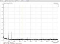
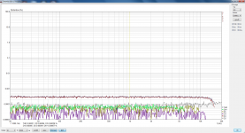
The second shot is the same setup except the AK4490 board driven at 192kHz. The only change I see is in the jitter. (Sensitivity to jitter)
You said that, because you saw the sidebands of 1KHz...
As you know, the ARTA has a specific jitter measurement at Gen pop-down menu (fs/4).
Use it with the window Hanning.
Yes, I'm still here wasting the precious last minutes before the flight today..
Hp, I'm intrigued by what you say about the none FFT window function!
Given that all windowing returns it's proper distortions exactly around the skirts, it sounds logical. How one can do that? I shall try your analyzer, shure.
And yes, Lemon, I was thinking of the 50Hz hum spurs appearing at the base. There are also other, for example non-harmonic at about ~~2.4kHz, which are connected to the USB bus activity, as far as I understood up to know. These things, the non-harmonic '''USB-spurs''' are also visibly changing between different USB cables (Ferrite clamp but not only) and physical topology of the dac.
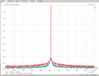
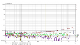
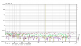
When I want to look at jitter, I do this, as in the comparison here. It is between the EMU1616m card in feedback, versus the AK4490 piloted by the Jlsounds+Crystek oscillators board. Red trace is the EMU, grey is AK4490.
The 11025 KHz carrier is always at -1dB, so the noise floor changes are correct with respect to each other (same resolution BW, aka sample length)
Yes, in the AK4490 trace there are some hum related sidebands.
Hp, I'm intrigued by what you say about the none FFT window function!
Given that all windowing returns it's proper distortions exactly around the skirts, it sounds logical. How one can do that? I shall try your analyzer, shure.
And yes, Lemon, I was thinking of the 50Hz hum spurs appearing at the base. There are also other, for example non-harmonic at about ~~2.4kHz, which are connected to the USB bus activity, as far as I understood up to know. These things, the non-harmonic '''USB-spurs''' are also visibly changing between different USB cables (Ferrite clamp but not only) and physical topology of the dac.
When I want to look at jitter, I do this, as in the comparison here. It is between the EMU1616m card in feedback, versus the AK4490 piloted by the Jlsounds+Crystek oscillators board. Red trace is the EMU, grey is AK4490.
The 11025 KHz carrier is always at -1dB, so the noise floor changes are correct with respect to each other (same resolution BW, aka sample length)
Yes, in the AK4490 trace there are some hum related sidebands.
Attachments
Last edited:
First with the Step Software (part of ARTA) make a THD vs Frequency test.
Then with the ARTA Software make a jitter test (Gen menu at the bottom).
Have in your mind that the Jitter test will be better with Hanning Window and as more FFT points as lower will be the Noise Level.
Then with the ARTA Software make a jitter test (Gen menu at the bottom).
Have in your mind that the Jitter test will be better with Hanning Window and as more FFT points as lower will be the Noise Level.
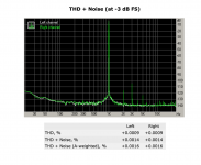
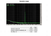
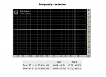
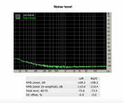
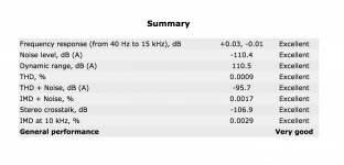
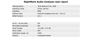
The specs I get on E-MU Tracker PRE with OS X 10.10.5 and RMAA via PlayOnMac.
Attachments
-
 Screen Shot 2015-08-22 at 6.49.37 PM.png168.2 KB · Views: 106
 -
 Screen Shot 2015-08-22 at 6.49.31 PM.png183.9 KB · Views: 116
 -
 Screen Shot 2015-08-22 at 6.49.25 PM.png228.5 KB · Views: 150
 -
 Screen Shot 2015-08-22 at 6.49.19 PM.png210.6 KB · Views: 163
 -
 Screen Shot 2015-08-22 at 6.49.13 PM.png210.5 KB · Views: 134
 -
 Screen Shot 2015-08-22 at 6.49.08 PM.png160.1 KB · Views: 492
 -
 Screen Shot 2015-08-22 at 6.48.59 PM.png210 KB · Views: 505
 -
 Screen Shot 2015-08-22 at 6.48.49 PM.png97.4 KB · Views: 505
 -
 Screen Shot 2015-08-22 at 6.48.28 PM.png105.7 KB · Views: 516
Ok, made some pics.
This one shows the output opamps replaced by OPA1652. Someone suggested OPA1612 might be better and I agree, but at 6 Euro's each they are about 3 times more expensive than the 1652.
View attachment 496609
What this does is reduce the upward sloping distortion somewhat, but the effect on total distortion is limited.
The next pic shows how the soft clipper is cut of from the circuit.
View attachment 496610
As this is basically a distortion engine for elevated input levels, as may be expected, taking it out of the circuit does lower distortion also at non-clipping levels. Also visible are the OPA1652's, replacing the JRC's. These have a form factor unique to JRC, but SOIC's align without problem.
Finally, capocide on numbers 26 and 40 eradicates the Whitlock style bootstrapping. For short measuring probes I see no advantage in this setup, but I can miss the positive feedback it gives for unbalances inputs like a sore tooth. It also eliminates the double bootstrapping to a node that is buffered from the input by U1 anyways.
View attachment 496611
Since the loop back distortion of this setup is almost an order of magnitude larger than that of the OPA1652 opamps I used, I don't think much can be gained by replacing them by 1612's or LM4562's, but than again, you just might push distortion even lower by a teeny-weeny bit. The ADC is specced as THD+N=-103dB, but S/N is -114dB. The DAC is -100dB and -120 dB respectively. So, in all likelihood, -114 dB is the absolute minimum distortion that can be achieved. With all these mods, the EMU almost reaches that level at some points.
Allready, I have changed the opamps (LME49720) and today I removed the soft clipper. I didn't cut the paths of R121, R122, R123 but I removed the resistors only.
I haven't the results that demonstrate at #112 post. In reality the step test before and after of this mod is almost the same, the same also at the levels of 2nd, 3rd harmonic of 1KHz thd test.
Vacuphile, at the post of 112 you said "removing R89 and R90, removing C40 so that this mystifying part of the circuit is out of the loop."
This is the only part that I haven't done, and I am thinking if this is important key to your modification.
Finally, I saw again the input schematic of sidiy.
I think that to my situation with LME49720 I need a new tweaking with the values around of opamps.
For the testing I removed the R89, R90 like Vacuphile and I repeat the testing.
With 96K sampling and -6dB signal the best step test that I have is the following. It is far away from the result of the Vacuphile test.
With the last mod (R89, R90) I see a small improvement at the 2nd and 3rd harmonic (THD Test) with 1 and 2 dB respectively.
The signal at the thd test was a 1Vrms (loop-back method).
Attachments
Lemon, I suppose this is with unbalanced input. With balanced input, the measurements are bound to be better. ...
I have forget it completely!
Here is a balance capture (-8dB generator level) of the completely unmodified right channel.
There is much difference btw unbalanced and balanced input. Unfortunately the input resistance of balanced input is only 1.5K via 1M of unbalanced input.
As I saw again, the Lynx E44 results, is also with balanced input and with -20db generator level)!
Attachments
As I saw again, the Lynx E44 results, is also with balanced input and with -20db generator level)!
Hi lemon, just for clarification the E44 results were made with the hardware set to output +20 dBu FS (full scale) and have an input sensitivity of +20 dBu FS. The generator level set in STEPS was the default -3 dB FS.
Thanks a lot for the crarification of Lynx results. I have wrong to my mind about this.
If I calculate them right, you had an almost 7.7Vrms output, that this produce a +20dBu input sensitivity?
Can you measuere with the -12dBu input sensitivity with balanced and unbalanced input?
If I calculate them right, you had an almost 7.7Vrms output, that this produce a +20dBu input sensitivity?
Can you measuere with the -12dBu input sensitivity with balanced and unbalanced input?
Can you measuere with the -12dBu input sensitivity with balanced and unbalanced input?
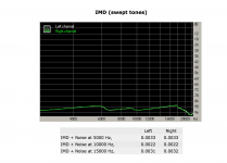
I've attached results for the E44 with the STEPS generator level at -8 dB FS and the E44 hardware at +20 dBu FS. The THD is dominated by 3rd harmonics while all others are at or below 0.0001%.
Lynx recommends that for unbalanced signals the signal should connect to "hot"/pin 2 as you'd expect, but the unbalanced ground should connect to "cold"/pin 3, and leave pin 1 floating. Since I'm testing in loopback this is essentially the same as balanced, so I'm not sure how I'd test that.
Attachments
Do you have a photo of your board? I'm especially interested in photos/ designation of D5/D8 D26..D31 elements (TVS diodes). Do they present on your board and all marked as 15D (as on mine)? I can't see exactly from your photos.. D26 seems 15D (that is 'usual' MMBZ15VDLT1) while D27 label looks like 5Dx that corresponds to MMBD914X (?.. strange!)After a full mod this is my latest measurement
Last edited:
Is there a recommended USB interface in 2016 for less than £120? It needs to have high dynamic range, 24/192 recording, and be able to handle high voltage inputs from DACs and other digital players. Here are my RMAA results for my Asus Xonar U7. The results are pretty good, but its maximum input voltage is only 1 Vrms.
An externally hosted image should be here but it was not working when we last tested it.
You try Steinberg UR22 MK2, very nice machine.
You try Steinberg UR22 MK2, very nice machine.
I can't seem to find any specs for that model online

Exist some tutorial about how to measure the distortion of the sound card? im interested to see if mine will be OK to measure amps/signals. I cant spend 600USD into a great lynx one :/
In theory mine have the following specs
Signal-noise ratio: 115dB(2CH ANALOG OUT)
Frequency characteristic: 0.3Hz~88kHz(2CH ANALOG OUT,+0/-3dB )
Digital IN sampling frequency: 32, 44.1, 48, 88.2, 96kHz
Digital OUT sampling frequency: 32, 44.1, 48, 88.2, 96, 176.4, 192kHz
Hardware requirement:
Corresponding type PCI (the Ver. 2.1 or more) the PC/AT compatible machine which has the bus slot
Processor: 32 bits (x86) or 64 bits (x64) processor; Above 800MHz (2000/XP), above 1GHz (Vista)
Memory: Above 128MB (2000/XP), above 1GB (Vista)
In addition: CD-ROM drive (necessity at time of software installation)
Input:
ANALOG IN x 2 (stereo RCA, internal connection)
MIC IN x 1 (φ 3.5mm/monaural)
DIGITAL IN x 1 (light)
Output:
2ch ANALOG OUT x 1 (stereo RCA)
DIGITAL OUT x 1 (light)
Last edited:
Exist some tutorial about how to measure the distortion of the sound card? im interested to see if mine will be OK to measure amps/signals. I cant spend 600USD into a great lynx one :/
In theory mine have the following specs
Signal-noise ratio: 115dB(2CH ANALOG OUT)
Frequency characteristic: 0.3Hz~88kHz(2CH ANALOG OUT,+0/-3dB )
Digital IN sampling frequency: 32, 44.1, 48, 88.2, 96kHz
Digital OUT sampling frequency: 32, 44.1, 48, 88.2, 96, 176.4, 192kHz
Hardware requirement:
Corresponding type PCI (the Ver. 2.1 or more) the PC/AT compatible machine which has the bus slot
Processor: 32 bits (x86) or 64 bits (x64) processor; Above 800MHz (2000/XP), above 1GHz (Vista)
Memory: Above 128MB (2000/XP), above 1GB (Vista)
In addition: CD-ROM drive (necessity at time of software installation)
Input:
ANALOG IN x 2 (stereo RCA, internal connection)
MIC IN x 1 (φ 3.5mm/monaural)
DIGITAL IN x 1 (light)
Output:
2ch ANALOG OUT x 1 (stereo RCA)
DIGITAL OUT x 1 (light)
Or at least another soundcard but not so expensive! 300USD range will be great!
Looking something for analize audio amps specs
For testing soundcards RMAA RightMark Audio Analyzer. Products. Audio Rightmark is the accepted (free) solution. Do some homework because its easy to get bad data for a variety of reasons but you should be able to get good results without much trouble. ARTA ARTA Software is the go to solution around here for measuring amps and speakers although I usually use other software.
For an internal soundcard that has good drivers and works well with most software the ESI Juli@ has worked well. There are better cards but they get expensive very fast and are MUCH harder to work with. For USB get an EMU 0404 and follow the various nots around here for modding/tweaking it to get the best results.
For an all in one solution the QA401 https://www.quantasylum.com/content/Products/QA401.aspx with its software is quite good and more troublefree as a system.
Also get or make a probe/interface because none of these will handle the full output of an amp.
For testing soundcards RMAA RightMark Audio Analyzer. Products. Audio Rightmark is the accepted (free) solution. Do some homework because its easy to get bad data for a variety of reasons but you should be able to get good results without much trouble. ARTA ARTA Software is the go to solution around here for measuring amps and speakers although I usually use other software.
For an internal soundcard that has good drivers and works well with most software the ESI Juli@ has worked well. There are better cards but they get expensive very fast and are MUCH harder to work with. For USB get an EMU 0404 and follow the various nots around here for modding/tweaking it to get the best results.
For an all in one solution the QA401 https://www.quantasylum.com/content/Products/QA401.aspx with its software is quite good and more troublefree as a system.
Also get or make a probe/interface because none of these will handle the full output of an amp.
Thanks for your help!
looks like E-MU 0404 are discountinued now, will try to measure my sound card
- Status
- This old topic is closed. If you want to reopen this topic, contact a moderator using the "Report Post" button.
- Home
- Design & Build
- Equipment & Tools
- USB vs PCIe Sound Card for audio analysis