I meant the main boards, not the Calvins. if you have J310 in the space marked J310 on the back of the shunt they are fine, if they are J113 you need to twist the legs. I assume you have used J113 because you've done the resistor swap to 1k from 3.3k. With the legs not twisted on these J113 you'll get voltage out of the shunt but not proper regulation.
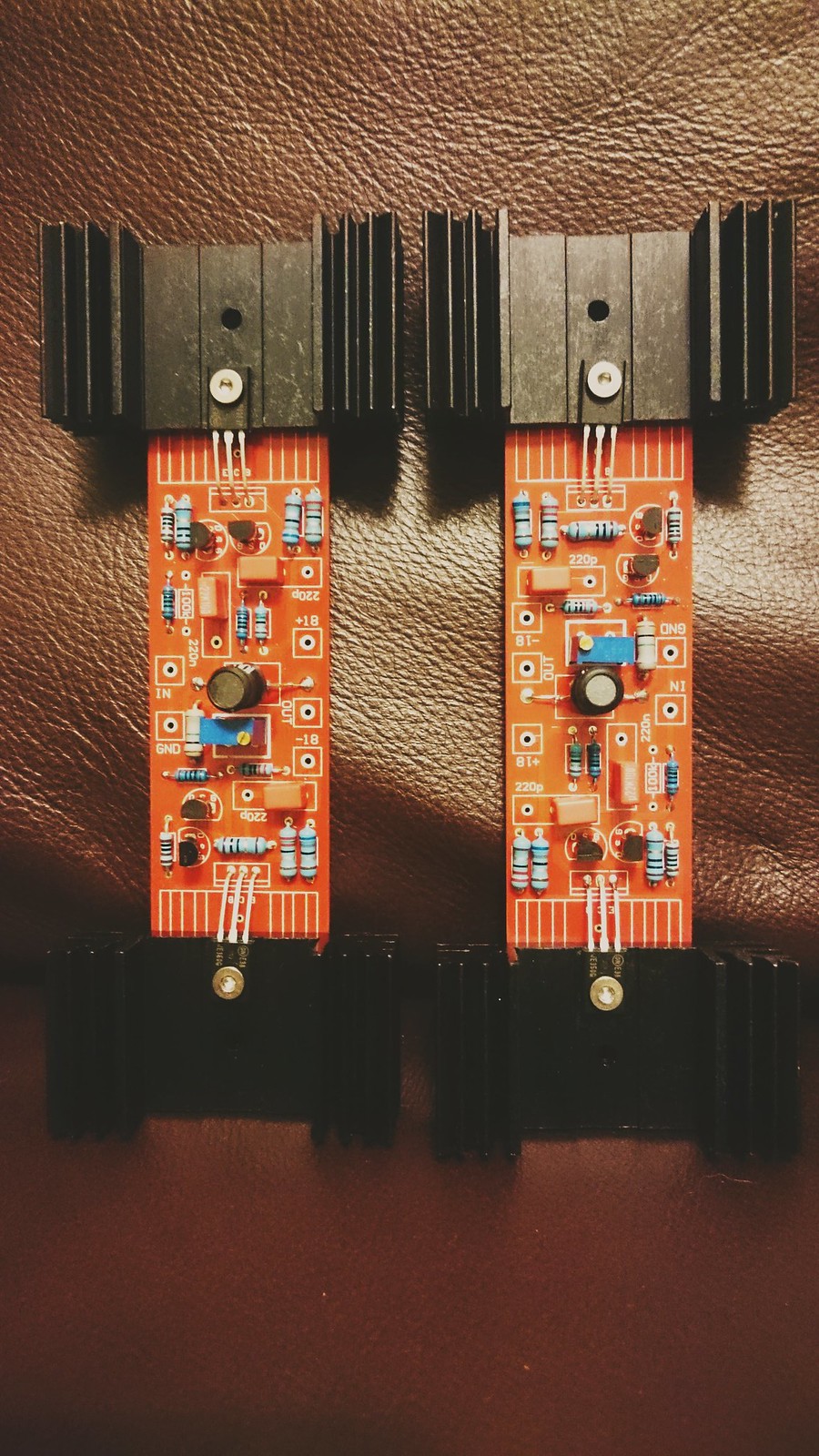
With the best will in the world those MJE350 look like a total clusterf_ck. If you drill a hole about 5mm into the heatsink at the opposite end to the existing hole, you can turn them round and use them without extending the legs.
I'd invest in a fibreglass bristle brush and get cleaning.
I haver spares of the small signal transistors on the Calvins if you finally track it down to those. Shouldn't be though, there were all measured and matched and handled carefully with static band.
Well I figured it out...with a bit of reading. I just stumbled on the posts in this thread another the leds not lighting,only the ones under the shunt heatainks...
Turns out the trim pot on the Calvin's needs tweaking all the way down...and then the leds come on. Something about the Calvin's taking too much current with the pot wound the wrong way.
I agree the 350s are a bit, err bodged, but my other half is home tomorrow ...I've have three weeks of soldering on the dining room table with out having to clear up everyday, so I was in a rush, bad me. I'm usual so anal about building boards that all the resistors and caps have to be the same way around, how bad it that...
All seems fine, playing music.")
Sent from my SM-G900H using Tapatalk
Turns out the trim pot on the Calvin's needs tweaking all the way down...and then the leds come on. Something about the Calvin's taking too much current with the pot wound the wrong way.
I agree the 350s are a bit, err bodged, but my other half is home tomorrow ...I've have three weeks of soldering on the dining room table with out having to clear up everyday, so I was in a rush, bad me. I'm usual so anal about building boards that all the resistors and caps have to be the same way around, how bad it that...
All seems fine, playing music.
Sent from my SM-G900H using Tapatalk
Si, thanks for all your help and the boards. I think it is all sorted out now, ta.
In the posts I read about the lack of LEDs and turning the trim pot up, there was discussion about whether the shunt was providing enough current.
Oh, and I can trim the ip/op offset on the board to zero.
I wonder of there is an measurements I could take to confirm that the Calvin board is working correctly?
And for completeness I will change the caps for the output transistors from 220pf to around 47pf.
I also wonder how much the inductor influences the sound. A few wire turns around a screwdriver doesn't gwt close to 10uH....
Anyway I still get sound. I've not spent enough time in front of the hifi to gauge whether the boards will be staying. The change from a phono stage made with a pair of Naim 323MC boards to the Paradise was like night and day, and tbh I'm still getting over that!!!!!
Thanks again for the help and the boards.
In the posts I read about the lack of LEDs and turning the trim pot up, there was discussion about whether the shunt was providing enough current.
Oh, and I can trim the ip/op offset on the board to zero.
I wonder of there is an measurements I could take to confirm that the Calvin board is working correctly?
And for completeness I will change the caps for the output transistors from 220pf to around 47pf.
I also wonder how much the inductor influences the sound. A few wire turns around a screwdriver doesn't gwt close to 10uH....
Anyway I still get sound.
I've not spent enough time in front of the hifi to gauge whether the boards will be staying. The change from a phono stage made with a pair of Naim 323MC boards to the Paradise was like night and day, and tbh I'm still getting over that!!!!!Thanks again for the help and the boards.
I have some 10uH coils from a hackercap/Voyager build...so I used a pair on those.Yeh I ended using bought in coils to get the required value. Measured better with them than the wire option.
I'm wondering though why such big heatainks on the Calvin's output devices. Mine don't even get warm, in fact tepid, if that! The shunt heatsink, well that is cooking, hotter than before I'd say...
Sent from my SM-G900H using Tapatalk
keywords: shunt regulator oscillation problem solution
Last month I bought a lightly-used Paradise/Calvin. It was built end of 2015.
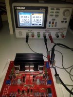
Upon arrival it appeared that all power supply rails were oscillating. There were traces of 5-6MHz all over the place, plus a larger-amplitude triangular component at 400kHz: 20mV on the regulator outputs, and 2V peak to peak on the regulator inputs (!!!).
Ten minutes with a circuit simulator revealed that this is caused in the shunt reg's current sources, due to trace inductance at their input. With the raw supplies in separate boxes and some 60 cm of cabling between them and the actual amplifier boxes you'll bet there is trace inductance. (Incidentally, the simulation both showed the 5-6MHz component and the 400kHz one.)
The simulation suggested a simple cure: just a little bit of capacitance between current source input and ground solves this rigorously. I added 470nF stacked film MKTs right at the transistors' collectors, and 22uF at the supply input connector.
This solved the problem indeed.
Last month I bought a lightly-used Paradise/Calvin. It was built end of 2015.
Upon arrival it appeared that all power supply rails were oscillating. There were traces of 5-6MHz all over the place, plus a larger-amplitude triangular component at 400kHz: 20mV on the regulator outputs, and 2V peak to peak on the regulator inputs (!!!).
Ten minutes with a circuit simulator revealed that this is caused in the shunt reg's current sources, due to trace inductance at their input. With the raw supplies in separate boxes and some 60 cm of cabling between them and the actual amplifier boxes you'll bet there is trace inductance. (Incidentally, the simulation both showed the 5-6MHz component and the 400kHz one.)
The simulation suggested a simple cure: just a little bit of capacitance between current source input and ground solves this rigorously. I added 470nF stacked film MKTs right at the transistors' collectors, and 22uF at the supply input connector.
This solved the problem indeed.
keywords: shunt regulator oscillation problem solution
Last month I bought a lightly-used Paradise/Calvin. It was built end of 2015.
Upon arrival it appeared that all power supply rails were oscillating. There were traces of 5-6MHz all over the place, plus a larger-amplitude triangular component at 400kHz: 20mV on the regulator outputs, and 2V peak to peak on the regulator inputs (!!!).
Ten minutes with a circuit simulator revealed that this is caused in the shunt reg's current sources, due to trace inductance at their input. With the raw supplies in separate boxes and some 60 cm of cabling between them and the actual amplifier boxes you'll bet there is trace inductance. (Incidentally, the simulation both showed the 5-6MHz component and the 400kHz one.)
The simulation suggested a simple cure: just a little bit of capacitance between current source input and ground solves this rigorously. I added 470nF stacked film MKTs right at the transistors' collectors, and 22uF at the supply input connector.
This solved the problem indeed.
Interesting.... this is a new one, has not shown up at least in my builds so far, and my PSU is 1.5m away..... thanks for the investigation and insight!
Me I had such problems too back when we built the first run, solved them with alternative Toshiba high Ft BJTs because some capacitors here and there did not help, but rather recently when mated with a heavier PSU box and different in-between cabling the instabilities came back. I did a heavy mod this time. I removed the whole CVS/CCS circuitry and replaced it with a single DMOS CCS. It involved some head scratching for creative wiring and other small alterations that I did not keep notes of. That was it, it plays no tricks any more. I don't know how it compares to an original since it also has less first stage AC grounding capacitance and bit altered RIAA curve anyway. I surely know it does not compare for looks... Oxidized and toothless. But it still works.
Attachments
Finally finished building my second Paradise board and I'm having problems with the shunt regulator. The two flanking led banks all light up. However the bank of six at the back glow at different intensities, the two inner leds are much brighter than the four, two pairs, outer ones.
I have the same issue in one of my builds..... Initially it burned a few leds... after rebuilding it seems stable now but two leds glow really strong at startup.
Mine turned out to be too low an input voltage. Once I'd replaced the transformers the LEDs all glow the same now.I have the same issue in one of my builds..... Initially it burned a few leds... after rebuilding it seems stable now but two leds glow really strong at startup.
Interestingly, with the Calvin boards installed the two banks of outer LEDs take about 20 secs from power on before they light up. I've read other people with the same issue in this thread...
Sent from my SM-G900H using Tapatalk
How did you find the oscillations?
I mean, directly with the oscilloscope or the sound was not great?
One channel emitted scratchy pulsating noises, so I started a full inspection.
The supply rails were at 18.6V. Turning these down to 18V removed the noises, but the oscillation remained.
Last edited:
Interesting.... this is a new one,
It is not a new one. If you trace back through this thread (which I did prior to starting my investigation proper) you'll see quite a few reports of exactly this oscillatory pattern.
That I could reproduce it in simulation without any effort is also telling.
Can you please specify exactly where I should position the c to stop oscillation?
Right between ground and the collectors of the first power transistors you encounter in the regulator's current source leg, i.e. the two outer transistors on the heatsink.
Mine turned out to be too low an input voltage. Once I'd replaced the transformers the LEDs all glow the same now.
The current through the outer LEDs is a function of the regulator output voltage, which is fixed, and the raw input voltage, which is an unknown and possibly a variable.
Right between ground and the collectors of the first power transistors you encounter in the regulator's current source leg, i.e. the two outer transistors on the heatsink.
So that's the D45H11 and D44H11 middle pins to gnd?
Something like ~2nF film cap, WIMA?
Sent from my SM-G900H using Tapatalk
- Home
- Source & Line
- Analogue Source
- Paradise Builders