In Tim's sch they don't exist, but are for current meter monitoring, also for tube fault short circuit current limit, value vary from 0.1 to 10 ohms depend on the tube, exist also in solid state output stage. Also some local feedback.
Since you touch on ecc83, have you use different brand? I can hear they all sound different. And also the driver, are you stuck with ef86 only? That is why others and I have suggested to use spectrum analyser to make check harmonics because it can give you many clues not just the sch also the tube itself. ECC99 has more odd harmonic than 6N6P, hence it sounds brighter in my amp. Please read this article for leisure. In my practical LTP sounds less congested the concertina. I also moved gNFB to 2nd grid of LTP, this has freed the input somewhat from very busy work. This the sim I already have, I can post it if anyone want to see.
What load impedance you have on the output? It's 32 ohms or higher? I have some findings on simulation on different loads, it may be a concern if you use higher load impedance, because totem pole has to be realigned to work on higher load, the current of top and bottom will not be fully symmetrical and maybe in Class A mode with one side conducts more than the other. So this is only simulation finding. It may concern me also as I intended to hook 32 ohms or more headphone directly to output, so I will hear really how it sounds as well as spectrum / scope monitoring. In the sim a small amout of NFB is feeded to top of 2nd LTP cathode, so the output current is synchronised and symmetrical.
I used 0,2 ohms in the upper anod just to pick-up the current while biasing . Do you think to be better on both cathodes? you have practicaly do this or you have a sim?
Yes, ecc83 of diffrent brands has diffrent sound (I tried Mullard, Philips, RFT, Tesla) the best detailed sound eas Philips miniwat. But also big improovment was achived since I separated the LTP PSU as well as the CCS and Bias PSU. Now I am working for a CCS with 2SK 117 I have big expectations. Send the sim you have done adjustmens.
For the moment I am listening my Quads on 8 ohms as they are, but my project goal is to change the imput transformers configuration to 32 ohms (nou thei have the prim. in paralel, then I shall swich them in series to get 32) If you have an ideea or sim about what can happens when totem goas to 32 ohms, please send it to me.
Thanks,
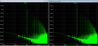
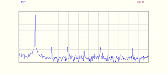
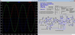
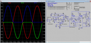
The one on the left is without cathode resistors, there is a little difference below 1khz.
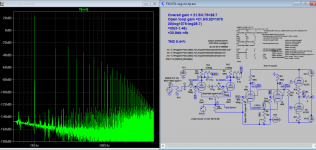
The FFT agreed with Tim's own measurement that 2nd harmonic is mostly canceled, therefore odd harmonic is always greater the even one. But I don't build Tim's, so I have doubt, can someone confirm on the harmonics. Are you able to alter the harmonics so that the even is more than odd one, that is preferable isn't it? My doubt is where the cancellation is taken place. In the sim I monitored every stage they has nearly same FFT pattern.
However, the FFT pattern changed if I add circuitry, the stages still have nearly same FFT pattern but the output FFT is not the same as Tim's.
So that is to confirm the harmonics pattern of original claim (false) before we can advance from here. But since we have spectrum analyser we can easily confirm that the preamp tube introduce tons of odd harmonics, if you don't do something about it will certainly appear in the output such as Tim's. Agreed?
For other FFTs such as CCS I'll follow up.
Attachments
Last edited:
The one on the left is without cathode resistors, there is a little difference below 1khz.
The FFT agreed with Tim's own measurement that 2nd harmonic is mostly canceled, therefore odd harmonic is always greater the even one. But I don't build Tim's, so I have doubt, can someone confirm on the harmonics. Are you able to alter the harmonics so that the even is more than odd one, that is preferable isn't it? My doubt is where the cancellation is taken place. In the sim I monitored every stage they has nearly same FFT pattern.
However, the FFT pattern changed if I add circuitry, the stages still have nearly same FFT pattern but the output FFT is not the same as Tim's.
So that is to confirm the harmonics pattern of original claim (false) before we can advance from here. But since we have spectrum analyser we can easily confirm that the preamp tube introduce tons of odd harmonics, if you don't do something about it will certainly appear in the output such as Tim's. Agreed?
For other FFTs such as CSS I'll follow up.
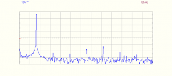
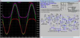
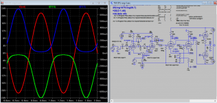
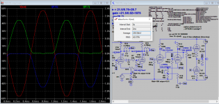
This is what I've got with a dummy load 8 ohms at low, half and full pover(40vpp)
But I have doubts about the accuaracy of my tonr generator. Measurements were done before splitting the PSU so I expect better figure as it is now
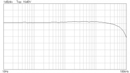
first is fft at 25w/8ohm, second is bode diagram at 3W/8ohm, third is fft at 1W/8ohms
It was the original Tim's design with Tesla e83cc, tesla ef86 and 6c33c not matched
Attachments
Last edited:
This is what I've got with a dummy load 8 ohms at low, half and full pover(40vpp)
But I have doubts about the accuaracy of my tonr generator. Measurements were done before splitting the PSU so I expect better figure as it is now
first is fft at 25w/8ohm, second is bode diagram at 3W/8ohm, third is fft at 1W/8ohms
It was the original Tim's design with Tesla e83cc, tesla ef86 and 6c33c not matched
Ya, look like you got rid of nearly all harmonics, does it sounds a bit dry or a little harsh with 5th dominance?
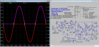
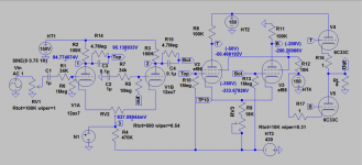
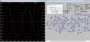
I just redo the sim for the 32 ohms load and correction of original, it's self explanatory, so please see attached. Also the re-route of gNFB going to grid od 2nd tube of 1st LTP, the the drive phase has to be swapped for it to work, and now is non-inverted amp. Now the volume control is out of gNFB path.
Attachments
Last edited:
Ya, look like you got rid of nearly all harmonics, does it sounds a bit dry?
I just redo the sim for the 32 ohms load and correction of original, it's self explanatory, so please see attached. Also the re-route of gNFB going to grid 2nd LTP, the the drive phase has to be swapped for it to work, and now is non-inverted amp. Now the volume control is out of gNFB path.
Yes, it was a little "dry" at the time. Now with all PSU individuated, sound has changed, also interesting change was after I replaced C1,2 with 3,4uF Solen fastcap.
As soon as I'll finished the ccs 2sk117 I shall releat the fft and bode.
Ya, look like you got rid of nearly all harmonics, does it sounds a bit dry or a little harsh with 5th dominance?
I just redo the sim for the 32 ohms load and correction of original, it's self explanatory, so please see attached. Also the re-route of gNFB going to grid od 2nd tube of 1st LTP, the the drive phase has to be swapped for it to work, and now is non-inverted amp. Now the volume control is out of gNFB path.
Why do you reed current on R17 + and R19- ?
Why do you reed current on R17 + and R19- ?
Don't exist! for monitor, only to plot the current phase.
Don't exist! for monitor, only to plot the current phase.
I ment why did you monitor + current on PSU raill and -current on the cathod ? there is anny clue?
I ment why did you monitor + current on PSU raill and -current on the cathod ? there is anny clue?
No, I got the drawing wrong, sorry about that. Here is the correction, thanks.
Attachments
No, I got the drawing wrong, sorry about that. Here is the correction, thanks.
On your remake 8, additional nfb is off ?
How do you explain the de-balancing of current on 32 ohms load ?
On 8 ohms load we must have 14 Vrms = 25W at 1,78AOn your remake 8, additional nfb is off ?
How do you explain the de-balancing of current on 32 ohms load ?
On 32 ohms load we must have 40 Vrms = 50W at 1,25A
On your sim there is not, why?
On your remake 8, additional nfb is off ?
How do you explain the de-balancing of current on 32 ohms load ?
Yes, it's normally off or you don't have to be bother if you are always < 8 ohms.
Ok, here is my explanation: When you apply NFB to a LTP at the shared cathode resistor, one leg will have NFB effect and this leg will have PF effect. Before we apply NFB, as in remake-7, the upper drive level is decreasing (due to increase in load value), in order to bring it to the same level as lower driver level, a proper adjusted NFB level will just boost the upper drive level and lower the bottom drive level so both tubes are now conducting equally.
I've got the point, but how did you calculate the nfb r/c ?
I've got the point, but how did you calculate the nfb r/c ?
I use LTSpice
") It will be double calculation one for NFB and other for PF with just on RC constant. R part and LTP cathode resistor forms a FB ratio..If I finally get to the details or someone can explain. The C part is simply to meet the bottom end once the R part is known, how using about a trimmer?
It will be double calculation one for NFB and other for PF with just on RC constant. R part and LTP cathode resistor forms a FB ratio..If I finally get to the details or someone can explain. The C part is simply to meet the bottom end once the R part is known, how using about a trimmer?I used 0,2 ohms in the upper anod just to pick-up the current while biasing . Do you think to be better on both cathodes? you have practicaly do this or you have a sim?
For the moment I am listening my Quads on 8 ohms as they are, but my project goal is to change the imput transformers configuration to 32 ohms (nou thei have the prim. in paralel, then I shall swich them in series to get 32) If you have an ideea or sim about what can happens when totem goas to 32 ohms, please send it to me.
Thanks,
A 1 ohm wirewound resistor used as current limiting in the cathodes of the power tubes should be helpful.
As you increase the load impedance, at some point you run out of voltage to drive it without also increasing the plate voltage on the power tubes. For this reason, most lower power OTLs seem to work best between 16-32 ohms. There is no reason to go over 32 ohms!
On 8 ohms load we must have 14 Vrms = 25W at 1,78A
On 32 ohms load we must have 40 Vrms = 50W at 1,25A
On your sim there is not, why?
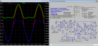
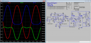
I don't drive it into clipping. It's 50W into 32 Ohms load if I did.
Attachments
Last edited:
I don't drive it into clipping. It's 50W into 32 Ohms load if I did.
Thanks, has been helpfool. As soon as I can finish the ccs matter, I'll try the local nfb as well as 1ohm cathod resistor. But one at the time.
I don't drive it into clipping. It's 50W into 32 Ohms load if I did.
Can you check for the remake 9 (50w/32ohms) the imput sinewave rms Voltage at 1k?
It cant be 0,75V. On my oppinion must be at least 1,5 Vrms.
Can you check for the remake 9 (50w/32ohms) the imput sinewave rms Voltage at 1k?
It cant be 0,75V. On my oppinion must be at least 1,5 Vrms.
1.4142V rms or 2V-p
1.4142V rms or 2V-p
Thanks again.
As I am still working on my banch at the ccs, I wander if you can simulate the output sine wave halves of the ecc83 at UP and BOT points (after R14/C3 and R15/C4) then I shall pick-up the real half waves, to have an ideea.
- Home
- Amplifiers
- Tubes / Valves
- New Tim Mellows OTL project