This is my rough setup, per channel (sorry for the crude diagram)
I use 30000μF per supply rail (plus some 0.1μF decoupling caps) for both channels, and a 200v / 330μF decoupling cap across the rails, right before the power transistors. Oh, my monitor is located about 30cm from the amp.
I use 30000μF per supply rail (plus some 0.1μF decoupling caps) for both channels, and a 200v / 330μF decoupling cap across the rails, right before the power transistors. Oh, my monitor is located about 30cm from the amp.
Attachments

Ok, now i'm getting somewhere.....
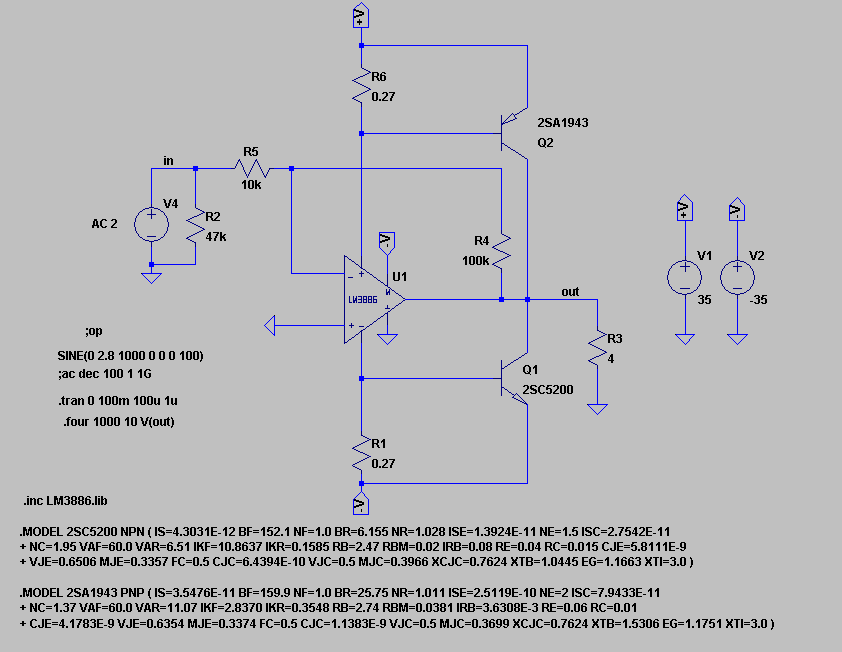
After a lot of experimentation and web research, this is where i have ended up.
I have implemented a biasing voltage through two IN4007 diodes, an act which COMPLETELY eliminated the crossover distortion. As you can see, there is no SYNC resistor at all, as it was getting very hot at higher volumes, and i think it was degrading the SQ!! Also, the feedback is not connected to the final output, but to the LM3886 output. Trust me, i have tried both and it works MUCH better this way!
The downside is that in this arrangement, the chip does not contribute at all to the output load, but after a lot of testing on 8 and 4 ohm speakers, it doesn't really have to...... There is plenty of RAW power from the transistors alone. No crossover distortion at all, just the natural clipping on ultra high volumes!!
Just to clarify something on the (awful) diagram, the resistor that connects the LM output to the diodes junction, is a 100ohm / 2watt resistor, but just as i'm typing, i have tried a 220 ohm in there and it seems to work even better!!
Now that this amplifier arrangement is working (for reasons i don't really understand, maybe the amp fairies have something to do), i am left wondering why the original (tried) circuit didn't work, and was misbehaving, oscillating and sucking (woofers)")
Now i am considering to use a separate, higher rail to rail voltage power supply, just for the output transistors, maybe something like +/- 50 volts!!
Hope it helps someone out there, cheers
After a lot of experimentation and web research, this is where i have ended up.
I have implemented a biasing voltage through two IN4007 diodes, an act which COMPLETELY eliminated the crossover distortion. As you can see, there is no SYNC resistor at all, as it was getting very hot at higher volumes, and i think it was degrading the SQ!! Also, the feedback is not connected to the final output, but to the LM3886 output. Trust me, i have tried both and it works MUCH better this way!
The downside is that in this arrangement, the chip does not contribute at all to the output load, but after a lot of testing on 8 and 4 ohm speakers, it doesn't really have to...... There is plenty of RAW power from the transistors alone. No crossover distortion at all, just the natural clipping on ultra high volumes!!
Just to clarify something on the (awful) diagram, the resistor that connects the LM output to the diodes junction, is a 100ohm / 2watt resistor, but just as i'm typing, i have tried a 220 ohm in there and it seems to work even better!!
Now that this amplifier arrangement is working (for reasons i don't really understand, maybe the amp fairies have something to do), i am left wondering why the original (tried) circuit didn't work, and was misbehaving, oscillating and sucking (woofers)
Now i am considering to use a separate, higher rail to rail voltage power supply, just for the output transistors, maybe something like +/- 50 volts!!
Hope it helps someone out there, cheers
Attachments

Sorry for spamming, but i just noticed that the lower output transistor (2SA1943) on the diagram is drawn incorrectly and should be reversed.
Anyway, i'm still wondering why the original circuit did not work. Shouldn't the NFB loop correct the crossover region nonlinearities of the extra output stage? I'm also wondering why my current arrangement works ok... considering that the output is no longer inside the NFB loop. Is this a class AB biased output stage? How does it work so linearly? At least to my (untrained) ears, i don't have an oscilloscope or special equipment, just a crusty old multimeter....
Anyway, i'm still wondering why the original circuit did not work. Shouldn't the NFB loop correct the crossover region nonlinearities of the extra output stage? I'm also wondering why my current arrangement works ok... considering that the output is no longer inside the NFB loop. Is this a class AB biased output stage? How does it work so linearly? At least to my (untrained) ears, i don't have an oscilloscope or special equipment, just a crusty old multimeter....
Sorry for spamming, but i just noticed that the lower output transistor (2SA1943) on the diagram is drawn incorrectly and should be reversed.
Anyway, i'm still wondering why the original circuit did not work. Shouldn't the NFB loop correct the crossover region nonlinearities of the extra output stage? I'm also wondering why my current arrangement works ok... considering that the output is no longer inside the NFB loop. Is this a class AB biased output stage? How does it work so linearly? At least to my (untrained) ears, i don't have an oscilloscope or special equipment, just a crusty old multimeter....
Κακώς...If you plan to go deeper to amps you must get one a.s.a.p. ...Oh! and you should built a dummy load before connecting any speaker to your projects...
Έχεις δίκιο συνονόματε Νάσο, αλλά που λεφτά για παλμογράφο;
Thanks Nassos, indeed i plan to go deeper in to building amps, among other hobby electronic projects of my interest, so a good ol' ANALOG oscilloscope is number one in my "equipment to acquire" list... Just waiting for a "good" deal on ebay to show up.
As far as dummy loads go, i already have a boxfull of power resistors ready to be used in a dummy load situation.
But my concern, on a more philosophical base, is that a purely resistive load is never the same as a real speaker, as it is missing the capacitive and inductive properties of a real speaker. I mean, it's good for testing as far as protecting an expensive real speaker, but IMO that's THE MOST to be expected from a dummy load. For example, in the situation i encountered a few posts back, the one with awfull oscillations and distortion on higher volumes, would it happen with a resistive dummy load?
My guts tell me that the reactive nature of a real speaker had a lot to do with it (apart from any bad design or layout)... What i'm trying to say is that MAYBE the oscillations would (erroneously) not show up on a resistive load test.
Of course, maybe that's all part of my imagination, at least 'till i get a scope and find out once and for all myself. Maybe the best dummy load is an inexpensive but beefed up speaker, or even an inexpensive sacrificial lamb, kamikazi speaker, ready to die in the name of "science"!
What's your opinion on this guys?
Ε,έχεις ένα δίκιο,αλλά τώρα που άνοιξε το e-bay χτυπάς αυτό και κάνεις δουλίτσα..: Popular Diy Oscilloscope Kit-Buy Cheap Diy Oscilloscope Kit lots from China Diy Oscilloscope Kit suppliers on Aliexpress.com
Dummy load is usefull instead of using speakers...On a suspect amp stage you can pump the volume up without the fear of burning your loudspeakers...Plus that if the signal underload seems good on oscilloscope,it sounds even better in real life!
Dummy load is usefull instead of using speakers...On a suspect amp stage you can pump the volume up without the fear of burning your loudspeakers...Plus that if the signal underload seems good on oscilloscope,it sounds even better in real life!
Thanks UltimateX86,
I have seen this before, very interesting concept of operation, but i rejected implementation for two reasons:
First, the lm3886 chip, unlike the tda729x, does not have completely separete supply pins for the input and output circuitry, and so i was afraid that the supply fluctuations (on which this idea is based on), would have a negative impact on SQ, as it would modulate the input circuitry supply stability... Am i somewhat right???? Is that what you are talking about AndrewT?
And secondly, i didn't want to mess up my nice pcbs by cutting the supply traces and fitting resistors in there.

Merry Christmyth everyone,
After extensive experimentation, i admit that i was not able to make a useful amplifier out of lm3886+power output transistors(2SA1943, 2SC2500). Whatever i tried, i had audible distortion either at low or either at high volumes.
Now that i have abandoned the project, i was thinking of possible reasons as to why it did not work according to plan. One thing that comes to mind, is that during the experiments, i had left the thiele/zobel network as it was firstly implemented, sitting between the output of the 3886 and the power transistors (i didn't want to rewire the whole pcb or cut any traces...).
I know that the thiele/zobel is supposed to be placed at the output of the amplifier (after the power trasistors for this project). Could this be the cause of my instabillity problems? Could the misplaced thiele/zobel act as a distortion generator in such a case (maybe like a tank oscillator or something)?
Dear friends
Anyone send me high end audio 5 band equalizer circuit
elliot has got good diagrams
Attachments
Looks like you can the data sheet looks the same except the 7295 is 80v max and 7293 is 120v and 7294 is 100v with no signal with a signal the max volts are slightly lower.please, to everyone. can tda7295 be used instead of tda7294?
Last edited:
That doesn't look like a particularly intelligent circuit, the 7294 is not providing any load power (and that seems to be its smallest problem).
I did make a PCB. It has shipped by slow boat - slower because of the holidays - and I should see soon enough if it works. However I am not using the circuits discussed here. Will post if/when I get any results to share.
I did make a PCB. It has shipped by slow boat - slower because of the holidays - and I should see soon enough if it works. However I am not using the circuits discussed here. Will post if/when I get any results to share.
- Home
- Amplifiers
- Chip Amps
- TDA7294 + Power Transistors AMP (TDA7293 to come also)