A sinewave is mathematically very precisely defined.
One attribute of a sinewave is that the peak of the waveform is exactly Sqrt(2) times the heating effect voltage (Vrms), i.e. Vpk = Vrms*1.4142.......
So, a 25Vac signal from a transformer secondary has a peak value of 25*sqrt(2) = 35.355........Vpk
The mains 115Vac sinewave has a peak value of ~162.6Vpk.
But the mains voltage is not "fixed", it varies from second to second and minute to minute.
Over the length of a day it could vary from 108Vac to 127Vac.
Now apply that varying mains voltage to a transformer rated as 115:25Vac and you will find that the output is NOT 25Vac most of the time.
There is another factor affecting the transformer's output:
A transformer has a "regulation" value.
The transformer output voltage varies with the load current that is passing.
At zero load current the output voltage is 25Vac times 1 plus the regulation.
i.e. for a 8% regulation transformer where 8% = 0.08 then Vout at zero load current equals 25Vac * {1+0.08} = 27Vac
Now apply 127Vac from the mains to that same transformer.
The maximum output voltage is 127/115*25*1.08 = 29.82Vac
The peak voltage of that maximum output is ~42.2Vpk
BTW, the Ebook you need is already written . It's called the internet. Go read, especially mains safety.
Last edited:
Use standard diodes unless very sure of the reasons. I often use a 1 uF class X2 cap for doing simple tests of rectifiers. The meter won't load it much. They are good for 630 VDC often and cheap. Be very careful if going that far, it is deadly to make a mistake. After that it is whatever the circuit requires. Put discharge resistor on. 5CR= 2 seconds would be about OK.
SOA. I always say to myself it is 1/4 of what I hope! The voltage recomendation is something friends and I felt to be true over the years. Proof is hard to come by. Class B and D amps seem to need this thinking. The conjecture is reactive loads can force the devices to see very high voltages that seem to defeat protection measures. I am convinced the transistor makers know this as no way would the devices be used at their supposed maximums when the modern 250V types.
My hope with the 30 VAC transformer is we don't go outside SAO. 35 VAC is too much for no real advantage. The 500 VA which most like myself can't resist buying further ensures it. The highly regulated 500VA 30 VAC has a small reserve of DC output above the 40 VDC required. It won't be much above a 120 VA 25 VAC that might just be workable. There is just enough overvoltage to run the amplified zener in most places.
I am not well grounded Andrew so mains are not a issue. I do greatly appreciate your input to my questions concerning my project and it does supply me with many opportunities to try to figure out just what the hell you are trying to tell me, how ever I still do not know where my 25 volts turns into 40 volts. I did get a telling response from atupi concerning my question. I think the old "keep it simple stupid" approach as a initial answer to Sufi my ignorance will be more helpful and then if you have the time to type I have the time to read. So take your blood pressure medicine and prepare for more. Maybe a sub thread is in order "FOR DUMMIES" P/S I'm a He, and signing up for a junior college course in guess what?
Andrew is very gifted at this stuff. Ian and me get the drift of it and hopefully boil it down to common thinking. Rules of thumb if you like. That's what we all get out of it. None of us I suppose ever get the chance to talk like this. Our Newby friends ask the most searching questions.
There are comprehensive texts by Bob Cordell and Douglas Self on audio amplifiers that are frequently referred to here. However, they are pitched at somewhat experienced DIYs and professionals and this means newbs need something intermediate that includes, rather than assumes the electronic basics.
A thread on a particular amplifier design or build topic is not the place to break off and go into the basics that successive new builders may each need, particularly when it's just ignoring what has all been said earlier in the thread and just hoping someone will do the spoonfeeding and search the usual material for them.
This massive site covers just about everything to do with linear Audio power amplifiers, projects and more:
Elliott Sound Products - The Audio Pages (Main Index) Go to the articles section and start with "beginners guide to...." articles. Most are pitched at what I imagine is US first year college level.
Enjoy, but note there is also a linked elementary audio electronics course at the Lenard site and many find this easier going to start with, due to the visual emphasis. Introduction: Greetings and introduction
ESP Audio is great advice. I have been in a situation where I train people. I learnt from the begining to go full strength with the answers as often people will understand. Half answers leave them halfway. That is worse than where they were. In my company we have to have quite difficult stuff built. The people who build things have to understand if they are to complete tasks. 90 % can be "do this and measure that". 10% has to be " this is how it works ".
A funny story. In the old company the lads who built things were the" no hope" lads from the local area. Apart from anything else the stories they told would not be suitable even for TV. One guy my age left because they so upset him. They didn't know me, I knew of them. One day I visited the factory and sat down with them. They misunderstood and started training me. Two hours later I got asked who the heck am I ? I am your boss was the answer. Alas their jobs were lost when the partners had a bust up. All got new jobs and quickly. I remember a phone call from one partner saying " I don't know what you said to the lads. You have them eating out of your hand ". Basically I wanted them to learn and they knew it. Also their stories were not too shocking to me. I always design things as if it's them and it never lets me down. What they didn't know they did learn. It was almost like wartime and they had to. I had to have a word with them about drugs. It was good enough for a film I think. Big D as he was called said " Nige your my dads age, wish he was like you". Proudest day of my life outside of my own kids. I doubt if any touch the stuff now. It never was a work problem , it's just I wouldn't have them in trouble. I wasn't heavy about it, just said they worked too hard to give their money away. In the end they did the work all by themselves and we think the factory never closed. Some were earning more than the boses. That was fine as the work was being done. They rotated themselves to get the best work rates. Some we think never went home. I know for a fact one didn't and we had to have a word. All very sad it ended. Me and the partners didn't need keys as someone was always there. Goodness knows what health and safety would say. It wasn't our doing and took time to see the time sheets to work out how our new production came about.
A funny story. In the old company the lads who built things were the" no hope" lads from the local area. Apart from anything else the stories they told would not be suitable even for TV. One guy my age left because they so upset him. They didn't know me, I knew of them. One day I visited the factory and sat down with them. They misunderstood and started training me. Two hours later I got asked who the heck am I ? I am your boss was the answer. Alas their jobs were lost when the partners had a bust up. All got new jobs and quickly. I remember a phone call from one partner saying " I don't know what you said to the lads. You have them eating out of your hand ". Basically I wanted them to learn and they knew it. Also their stories were not too shocking to me. I always design things as if it's them and it never lets me down. What they didn't know they did learn. It was almost like wartime and they had to. I had to have a word with them about drugs. It was good enough for a film I think. Big D as he was called said " Nige your my dads age, wish he was like you". Proudest day of my life outside of my own kids. I doubt if any touch the stuff now. It never was a work problem , it's just I wouldn't have them in trouble. I wasn't heavy about it, just said they worked too hard to give their money away. In the end they did the work all by themselves and we think the factory never closed. Some were earning more than the boses. That was fine as the work was being done. They rotated themselves to get the best work rates. Some we think never went home. I know for a fact one didn't and we had to have a word. All very sad it ended. Me and the partners didn't need keys as someone was always there. Goodness knows what health and safety would say. It wasn't our doing and took time to see the time sheets to work out how our new production came about.
Last edited:
In IRC style block resistors, I've only encountered wire or thick metal ribbon . I haven't seen the insides for some years but I imagine you saw something like the pic below. If it was metal oxide compound and not metal ribbon, I guess my presumption that common ceramic block resistors are ww is not always so. If some are also falsely specified as ww, it will be cause for complaint.....I opened up a damaged ceramic cased wirewound to discover it was a metal oxide helix wound/cut on a very small diameter ceramic substrate with pressed on metal end caps welded to copper tails.....A laser cut film could very easily be a opposing double helix type to reduce inductance. Has anyone seen these advertised, or claimed by the manufacturer?
Some ww resistors sold as low inductance types are actually bifilar wound. Would that be the form of double helix you mean? I haven't heard of film resistors being spiral cut in that way though.
An externally hosted image should be here but it was not working when we last tested it.
Thank you Nigal, Thank all of you for that matter! In retrospect I chose this project and this thread because of the name given to it "NAP-140 Clone Amp Kit on Ebay" "A good project for the newbie" and it is. It is the visual as well as the mental aspect of building of the project that present the questions. Remembering that this is my first Endeavor, given everything up to and including the theory of relativity I can loose the question in the answer, Given a basic verbal explanation to a question and a specific, use this component of this value, it will best serve your needs, that understanding will lead to better informed questions as to my needs and why they are my needs. With my budget I cant assume I understand some of the response I get, hence the simplistic questions.ESP Audio is great advice. I have been in a situation where I train people. I learnt from the begining to go full strength with the answers as often people will understand. Half answers leave them halfway. That is worse than where they were. In my company we have to have quite difficult stuff built. The people who build things have to understand if they are to complete tasks. 90 % can be "do this and measure that". 10% has to be " this is how it works ".
A funny story. In the old company the lads who built things were the" no hope" lads from the local area. Apart from anything else the stories they told would not be suitable even for TV. One guy my age left because they so upset him. They didn't know me, I knew of them. One day I visited the factory and sat down with them. They misunderstood and started training me. Two hours later I got asked who the heck am I ? I am your boss was the answer. Alas their jobs were lost when the partners had a bust up. All got new jobs and quickly. I remember a phone call from one partner saying " I don't know what you said to the lads. You have them eating out of your hand ". Basically I wanted them to learn and they knew it. Also their stories were not too shocking to me. I always design things as if it's them and it never lets me down. What they didn't know they did learn. It was almost like wartime and they had to. I had to have a word with them about drugs. It was good enough for a film I think. Big D as he was called said " Nige your my dads age, wish he was like you". Proudest day of my life outside of my own kids. I doubt if any touch the stuff now. It never was a work problem , it's just I wouldn't have them in trouble. I wasn't heavy about it, just said they worked too hard to give their money away. In the end they did the work all by themselves and we think the factory never closed. Some were earning more than the boses. That was fine as the work was being done. They rotated themselves to get the best work rates. Some we think never went home. I know for a fact one didn't and we had to have a word. All very sad it ended. Me and the partners didn't need keys as someone was always there. Goodness knows what health and safety would say. It wasn't our doing and took time to see the time sheets to work out how our new production came about.
Thanks again.
What seems to have happened with this kit is a chance to walk in the same shoes as Mr Vereker in 1976 or there abouts. We are forced to look again as so many things work against it being a real Naim amplifier. Much in the same way as making a New World wine. Whilst not identical it is in the spirit of.
There was a simple answer to the 40 VDC question. 25 VAC and > 160 VA is a safe bet. Some go to 500 VA in the spirit of Naim. I would use a ready made 35 AMP diode bridge as these are cheap. This one would do as it is very cheap. Some fancy diodes seem worse to me. 50 VDC 22 0000 uF for the 500 VA and 50V 10 000 uF if 160 VA to 300 VA. You might only get 35 VDC full load. That is safe and less risk than 45 VDC. This is more true if risking BC239 instead of BC237/550C as TR1/2.
http://www.rapidonline.com/Electron...12?sourceRefKey=lIjs8z8s9&filterSearchScope=1
Last edited:
I had gathered that, seeing pictures of the various builds online including including the original. I am finding variations even in the ebay "clone"s themselves, the kit that I ordered has caps in it that are the same value but much smaller physically, the three 50v 10u caps are 8mm in dia. as opposed to the approx 16mm pictured, this makes me wonder should I install a good quality cap of the size that is indicated in other pictures and the printing on the PSB itself? This is the blue PSB $24.00 US free shipping version. That said I have tested the components that I am able to and have had no issues. I have ordered the other channel (kit) hopefully it will at the least be a clone of the one I have assembled. The above is info I can apply to place the order.What seems to have happened with this kit is a chance to walk in the same shoes as Mr Vereker in 1976 or there abouts. We are forced to look again as so many things work against it being a real Naim amplifier. Much in the same way as making a New World wine. Whilst not identical it is in the spirit of.
There was a simple answer to the 40 VDC question. 25 VAC and > 160 VA is a safe bet. Some go to 500 VA in the spirit of Naim. I would use a ready made 35 AMP diode bridge as these are cheap. This one would do as it is very cheap. Some fancy diodes seem worse to me. 50 VDC 22 0000 uF for the 500 VA and 50V 10 000 uF if 160 VA to 300 VA. You might only get 35 VDC full load. That is safe and less risk than 45 VDC. This is more true if risking BC239 instead of BC237/550C as TR1/2.
DC Components KBPC5006 Bridge Rectifier 50A 600V | Rapid Online
Last edited:
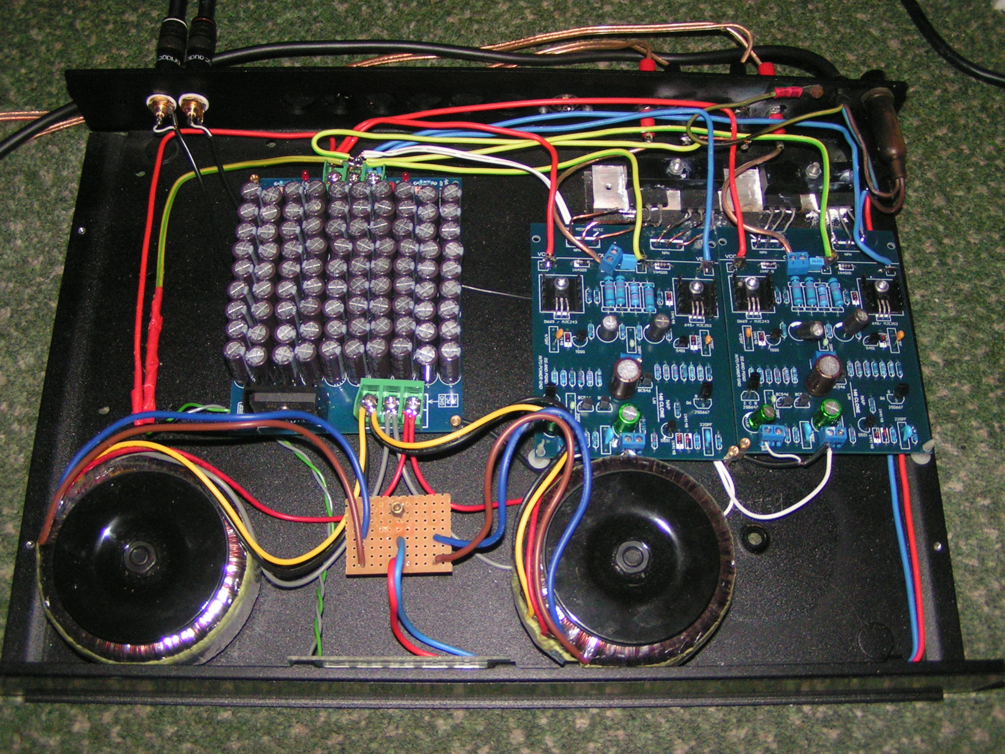
Hi barry.childs, good to see your posts again. As a matter of interest, how is your clone build performing and what are your thoughts on the sound quality some years later? I hope you don't mind me re-posting your amazing build pic, from back at #702.
Hi also, Less Opinion - The shrunken capacitor sizes now seen everywhere are a feature of modern electrolytic caps. The technology has changed, as you would expect over 40 years or so and parts are now much smaller and cheaper. The pressure on size, cost and the shift to surface-mount technology has spilled over into through-hole parts too so when you see clones and replacement parts in old designs, you also see ridiculously high cap values used to maintain the beefier looks of the original. Some also claim better bass sound for anything built with larger than designed cap. values but that assessment will often carry the usual "bigger is better" expectancy bias or just reflect on little test experience.
Hi also, Less Opinion - The shrunken capacitor sizes now seen everywhere are a feature of modern electrolytic caps. The technology has changed, as you would expect over 40 years or so and parts are now much smaller and cheaper. The pressure on size, cost and the shift to surface-mount technology has spilled over into through-hole parts too so when you see clones and replacement parts in old designs, you also see ridiculously high cap values used to maintain the beefier looks of the original. Some also claim better bass sound for anything built with larger than designed cap. values but that assessment will often carry the usual "bigger is better" expectancy bias or just reflect on little test experience.
I will leave that question for another time or let others do it first.
I find I have enough parts to build a test rig.
http://docs-europe.electrocomponents.com/webdocs/0111/0900766b80111b4e.pdf
500 VA 25 V full load 6% regulation.
Capacitors 22 000uF 40 VDC computer grade Samwa screw terminal >10 amp ripple.
200V bridge rectifier 35 amp with standard diodes.
253 VAC (126.5 USA) 29.3 VAC 40.1 VDC
245 VAC (122.5 USA) 28.4 VAC 38.8 VDC
230 VAC (115.0 USA) 26.7 VAC 36.4 VDC
207 VAC (103.5 USA) 24.0 VAC 32.6 VDC
All the above are taken as best I could on a real power amp on a typical standby load. The meter is a low cost one typical of the ones most reading this would have. There might be small errors due to the variac changing whilst taking a reading.
What comes out of this is the 160 VA that is 9% regulation is at the absoulute limit of a BC550C or BC237 at 45 VDC Vceo. If BC239, rather you than me.
It is said the USA can go as high as 130 VAC. If so we hit 43 VDC and we need to be careful. Please sample the house voltage. A USA transformer supplier who knows the requirements might be best.
In view of this I think it prudent to fit known to be genuine BC546 into TR1/2. The noise levels are as good as the standard fit devices.
I would fit 50 VDC capacitors in this example.
ON SEMICONDUCTOR - BC546B - Bipolar (BJT) Single Transistor, NPN, 65 V, 300 MHz, 625 mW, 100 mA, 150 | CPC UK
If you wonder why the DC voltage is higher than the AC the reason is simple. The AC is the heating effect a sine wave has through a resistor or heating device. If you like the peak of the sine wave is cut off and distributed in the valley as if rocks. The level height is the heating effect. Picture it as a road that goes at this average height as when railroads were built. As the capacitors charge up it is as if we made the new road from peak to peak. If we look at a sine table 45 degree is at 0.7071. 45 degrees is exactly half a sine wave rotation between 0 and maximum ( or max to 0 ). The values can be between 0 and + peak and 0 and - peak values. For our needs that isn't the picture we need. All we need is the 0.7071. That cames from a 45/45 triangle.
If we take our 40.1 VDC we might think the AC will be 28.36 VAC. What we saw was 29.3 VAC. That's rather good ( or not ) as the bridge rectifier has losses. These grow as power used gets larger. We also can not exspect a cheap meter to be to lab standards. Usually they are not too bad. What we care about is the TR1/2 and the PSU capacitors are at comfortable standby voltages. In this example they are at the limit. This might surprise people that the amplifier is at one type of maximum risk when doing nothing. I have had failiures doing this. I lost 16 x 2N3055 at 80 VDC doing nothing ( 76.4 VDC typical in truth ). Quad were right at 67 VDC. Internet "experts" were wrong.
Andrew you are right. The company Tiger from Peterborough seen to be able to make old style.
This is my local company ( 10 miles ). They are very OK and good prices. UK designed and made in China. As off the peg designs go they are for a modern device rather good. I seems to get good 260 V results from them which is a good sign. I often test to 270 V.
http://www.rapidonline.com/pdf/82719.pdf
A question that will come up is what type of rectifier? There are even considerations of noise polution to consider if they are a retail product. The boss of Naim was so upset about this he spoke out. He prefered simple diodes as descibed so far. What he hated was devices called snubbers. These often are 10 nF caps between each diode ( 4 ). As a compromise 1 x 10 nF on AC input close to the rectifier bridge.
Mr Vereker was both wrong and right. It was noted other make equipement often didn't like Naim amps. The reason could be diode noise.
Some recomend Schottky diodes and others fast diodes. Forgetting voltages I prefer standard diodes. The exception being fast diodes with soft recovery. As far as I can tell these have internal snubbing or something. Whatever it is it reduces trouble.
The problem with the conventional snubber or near snubber is it doesn't snub. It causes a short duration big peak spike to becomes a nasty series of smaller and lower frequency peaks. If ever there was a better way of screwing up I can't imagine.
Propper snubbers can be made. Best not go there I would say. It is easier to send a rocket to the Moon in matamatical terms.
As far as I know soft recovery diodes solve the problems and might even please the silly people at CE who think they understand electronics. The arguement even went that an AM tuner might be noisey if in a stack. I found 10 cm spacing cured that! The modern arguement is that computers might get corrupted by this diode noise. Mostly that's untrue. Ethernet on mains is not a lot different.
http://www.vishay.com/docs/94047/hfa08tb6.pdf
Only on Rotel when like RA820. The fuse has two mystery terminals and a link wire. Rotel gave out the imformation to service engineers to do a test repair, then for safety replace. Philips had a repairable thermal fuse in a PSU for cassette recorders and general uses. The design was two spring copper wires with a soldered end in a plastic holder. The end could be repaired. It was obviously for repairs as the device was in a secret molding rather than trapped in the windings. The way it was made offered the chance to repair it without buying a new part. It was almost impossible to make a bad repair as the original idea was so simple.The solder was a small blob at the tip. Just some flux to reuse the solder if low melting type.
Interesting
No load on either test. Vdc went from 26Vdc unfiltered to 38.1 with with the addition of a 35 volt 220uF capacitor. (I need a bread board) Can I assume the amount of capacitance is going to dictate the Vdc out put?
Add an capacitor to that across +/- Vdc and it will show the filtered vdc value.
No load on either test. Vdc went from 26Vdc unfiltered to 38.1 with with the addition of a 35 volt 220uF capacitor. (I need a bread board) Can I assume the amount of capacitance is going to dictate the Vdc out put?
- Home
- Amplifiers
- Solid State
- NAP-140 Clone Amp Kit on eBay