Thank you for your understanding X and Britt.
To keep easier any exact distances only need putting double nut above and below the flat surface which will prevent it from moving at all the whole set.
This method can also prevents do an excessive compression that could deform the wall of the horn, as may be pressed exactly the precise amount and then performing the final tightening of the double nut then the press over the horn wall remain the same forever.
I agree than put exact amount of press to not deform wall of horns will be little tricky but i think its horn walls are enough strong to do easily and correctly.
Besides the foam to which I refer si quite rigid and even more when it is little compressed so it is set once the double nuts are tightened all has a very high rigidity and inmobility.
Believe that I did something similar in the pipe plumb and there are 2 atmospheres pressure liquid and the foam board joint is working without losses from the first day.
But i agree Britt opinion that this method maybe best fit to prototyping but I do not rule out at all for a final construction with the proper foam and known the exact strength of the walls of the horn once chosen. If the horn is metal build would not worry at all about their deformation and neither form plastic materials which are normally built since the clamping force is distributed over the entire surface of contact of the foam which in turn will be hughe of the total own of horn.
But anyway only a idea that will be used some day in one build.
Regards
Last edited:
Thank you for your understanding X and Britt.
To keep easier any exact distances only need putting double nut above and below the flat surface which will prevent it from moving at all the whole set.
This method can also prevents do an excessive compression that could deform the wall of the horn, as may be pressed exactly the precise amount and then performing the final tightening of the double nut then the press over the horn wall remain the same forever.
I agree than put exact amount of press to not deform wall of horns will be little tricky but i think its horn walls are enough strong to do easily and correctly.
Besides the foam to which I refer si quite rigid and even more when it is little compressed so it is set once the double nuts are tightened all has a very high rigidity and inmobility.
Believe that I did something similar in the pipe plumb and there are 2 atmospheres pressure liquid and the foam board joint is working without losses from the first day.
Double nut is a great idea. This is sounding better now given your experience with it holding watertight seal with plumbing.
The compressed foam seal can work well and provides mechanical stability to support the wooden board.
It is clean and glop free!
Let it harden and then screw the wooden driver board to the formed flat surface rather than relying on the putty to bond the wood to the horn.
My plan is to use 35mm screws to secure woofer - they will pass through woofer bezel, through ply ring, through MDF plate, and into epoxy. Thereby securing the whole as a single unit.
Although the epoxy I used should provide a stronger bond than the MDF anyway!
I have also bought a couple cans of expanding structural foam - (which I think is what is being discussed here) and will be smoothing over all the gaps then cutting/smoothing to make a neater job and further damp the horn.
I have to be honest though, I have used expanding foam a lot before in various DIY constructions - it may be OK for sealing a joint in a plumbing waste pipe, but I do not think it would be strong enough for two high excursion woofers at x-max!
Celestion AN2775 2-3/4" Full Range Compact Array Driver
This little guy and its smaller 2" brother often get overlooked.....the 2" sounds INCREDIBLe
This little guy and its smaller 2" brother often get overlooked.....the 2" sounds INCREDIBLe
My plan is to use 35mm screws to secure woofer - they will pass through woofer bezel, through ply ring, through MDF plate, and into epoxy. Thereby securing the whole as a single unit.
Although the epoxy I used should provide a stronger bond than the MDF anyway!
I have also bought a couple cans of expanding structural foam - (which I think is what is being discussed here) and will be smoothing over all the gaps then cutting/smoothing to make a neater job and further damp the horn.
I have to be honest though, I have used expanding foam a lot before in various DIY constructions - it may be OK for sealing a joint in a plumbing waste pipe, but I do not think it would be strong enough for two high excursion woofers at x-max!
Hi Bush.
Im follow here your great work and you are a master that really know you must work a loudspeaker enclosure and sure you are rigth about the foam maybe would be not enougth strong for that build.
So im keep here learning with you and all other like X and all other that post in this forum.
I wish the best !
Regards
My plan is to use 35mm screws to secure woofer - they will pass through woofer bezel, through ply ring, through MDF plate, and into epoxy. Thereby securing the whole as a single unit.
Although the epoxy I used should provide a stronger bond than the MDF anyway!
I have also bought a couple cans of expanding structural foam - (which I think is what is being discussed here) and will be smoothing over all the gaps then cutting/smoothing to make a neater job and further damp the horn.
I have to be honest though, I have used expanding foam a lot before in various DIY constructions - it may be OK for sealing a joint in a plumbing waste pipe, but I do not think it would be strong enough for two high excursion woofers at x-max!
Sounds good. What is your plan for a temporary baffle/box to allow woofer testing?
Epoxy putty works well for attaching wood to plastic, and can fill large gaps, but is expensive.Sort of an open question for other members as a brainstorn here: are there other ways to interface a flat plywood driver mounting board to a curved plastic waveguide wall securely?
Attach wood panel all the way around horn like a box/dam and fill space with polyester hardening resin? Plaster of Paris? Cement? etc.
After laminating pieces of plywood to conform to the rough horn shape, it is fairly quick work using a belt sander with 50 grit to finish shaping it to conform closely to the horn surface, minimizing the amount of epoxy needed for the joint.
That said, easier to build a four sided conical horn of the desired dispersion pattern, though with a conical expansion high frequency dispersion is limited to the driver's native response, assuming the throat is the diameter of the cone (less surround).
Attachments

Sounds good. What is your plan for a temporary baffle/box to allow woofer testing?
For that I have ear marked a roll of duct tape, some rockwool, and a storage box.....
")
I have some things done, however I am to busy now with outher things, so I do horn between it..
I have round of the throat, it did extend to 4 khz, and graph is with a K-tube in front.
see also distortion part.
regards
I have round of the throat, it did extend to 4 khz, and graph is with a K-tube in front.
see also distortion part.
regards
Attachments


Last edited:


OK couldn't help myself - these are some woofer measurements with the whole horn just wrapped in blankets - so the woofer has no real enclosure at all. Just blankets to try to minimize cancellation from the back wave.
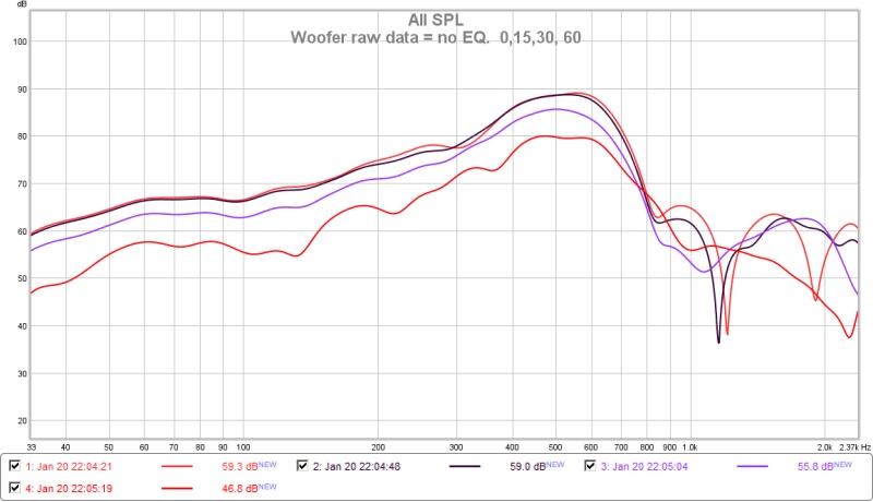
Interesting that the acoustic roll off in the HF is at closer to 700Hz which means that I underestimated the volume of the chamber formed by the cone and horn wall. A larger volume will push it down. This may be good as it helps you get to the -24dB/oct at 500Hz acoustical XO you need for the Harsch later on. Perhaps only a -12dB/oct electrical HPF needs to be applied? It also reduces HD from the woofer from leaking out at HF's.
Nice work!
The blankets worked somewhat as I think the roll off would have been closer to 850hz without.
Last edited:
FTH142 and DC200-8's arrived
Got a package today
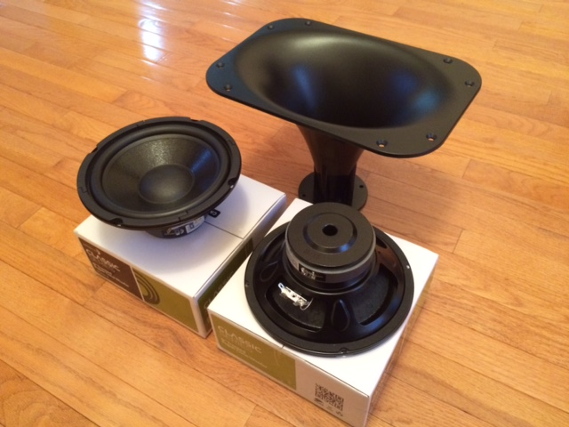
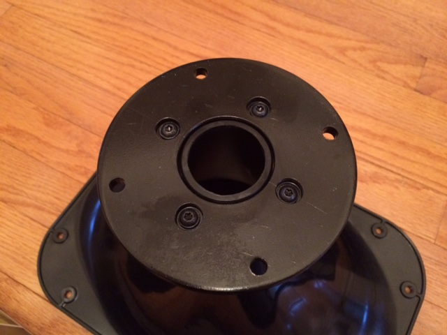
The WG flange on the FTH142 is made of steel. Good thing I am 3d printing a smooth throat adapter - no way to file that stuff. The steel flange is bolted onto the WG which has that thin lip of ABS plastic that slips into the hole on the WG flange.
Got a package today
The WG flange on the FTH142 is made of steel. Good thing I am 3d printing a smooth throat adapter - no way to file that stuff. The steel flange is bolted onto the WG which has that thin lip of ABS plastic that slips into the hole on the WG flange.
Attachments


Whoa!!! You are getting -45dB HD at 40Hz and 85dB??? Could it be that it will go full range sort of like what I discovered with my uTrynergy in the open back configuration? It also went down to 40Hz, but I was not getting super clean HD like this. Your SB23's are obviously superb low distortion drivers.
And this is only 1 woofer!
Nice work again!
How much EQ are you applying?
And this is only 1 woofer!
Nice work again!
How much EQ are you applying?
Looks like they are going to be loud and clear! Looking very good so far!
I hope this construction method will hold and kept my fingers crossed. Looks like a lot of members did that as it seems to have helped.
I'm curious how the enclosure is going to look. I'm hoping to see huge round-overs wherever possible on the front when you're done. Nice and smooth...
I hope this construction method will hold and kept my fingers crossed. Looks like a lot of members did that as it seems to have helped
.I'm curious how the enclosure is going to look. I'm hoping to see huge round-overs wherever possible on the front when you're done. Nice and smooth...

- Home
- Loudspeakers
- Multi-Way
- A Bookshelf Multi-Way Point-Source Horn