Starting this thread hoping to get precious input about a mute timer.
I have a double input preamp and use a relay to switch inputs (The two inputs have different gains), when I switch inputs there is a loud thump on the output so I need a muting circuit that should work just during switch time.
For the muting circuit (that shorts the output to gnd) I use a 555 in monostable mode that drives a relay directly.
This 555 closes the mute relay immediately after the push button is closed and opens it after 2 seconds.
Now I need a timer to actuate the input relay after the output is muted so I used a 555 wired as flip flop that actuates a delayed circuit.
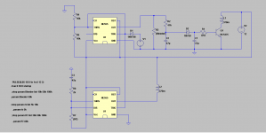
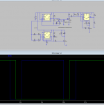
Please have a look at the schematic.
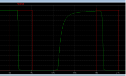
My doubts are related with the delay circuit that seems to work in simulation.
I have a double input preamp and use a relay to switch inputs (The two inputs have different gains), when I switch inputs there is a loud thump on the output so I need a muting circuit that should work just during switch time.
For the muting circuit (that shorts the output to gnd) I use a 555 in monostable mode that drives a relay directly.
This 555 closes the mute relay immediately after the push button is closed and opens it after 2 seconds.
Now I need a timer to actuate the input relay after the output is muted so I used a 555 wired as flip flop that actuates a delayed circuit.
Please have a look at the schematic.
My doubts are related with the delay circuit that seems to work in simulation.
Attachments
Last edited:
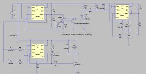
V1 sends a pulse thru D1 and "hopefully" acts as a door bell push button.
U1 (wired as a monstable) closes relay L2 (muting).
U2 (wired as flip flop) starts delay circuit that should close relay L1 (input switch) aprox 1 sec after relay L2 is closed.
After 3 secs, U1 will time out and open relay L2 (muting).
L1 on switching delay is provided by C2 / R2 / D2 (4.7zener)
Now, when I want to switch L1 (input) off, it should also be delayed and that is why I have the C1/R1 installed.
When U2 output goes low, C1 should keep Q1 open for 1 sec and so delay the opening of relay L1. (During that process, muting relay L2 should also be closed).
As the transistor starts to turn on it draws current.
that current slows down the rate of increase of voltage on the timing capacitor.
This holds the transistor in the part on condition for a longer time and potentially could overheat the switching transistor.
To avoid heating the switching transistor you need to ensure that the switcher is saturated and you want to get to that condition quickly.
Saturation is defined as Ic:Ib ~ 10:1.
If you know the relay current (=Ic), you can estimate the base current to achieve cold/saturated operation by passing 10% of Ic into the base.
What happens to the Vdrop of R2, if an ADDITIONAL current of Ic/10 is drawn by Q1base?
The easy way to ease this problem is to ensure that the ADDITIONAL current draw as the switcher turns on is kept low in comparison the the rapidly decreasing current passing through R2.
The way to do that is to add a driver transistor to "multiply" the current drawn from R2 and send that with a highish hFE to Q1 base.
You can add in that driver in a variety of locations in your diagram.
Use LTspice to examine the voltages and timings of the current changes for the different locations.
Try BC550b (use Cordell's BC550C) before D2, after D3, after C1
Feed the collector current through a resistor tied into the 12Vdc supply.
Have you looked at what effect leakage of C2 has on the timing?
Is there a condition of low supply voltage combined with high leakage current that could prevent triggering of the relay?
YOU have to check that for all operating conditions and tolerances that the voltage on C1 and/or C2 rises fast enough to pass through the triggering voltage required by Q1
Last edited:
BTW,
I think the "thump" could be due to the CHANGE of gain not the actual switching between sources.
The change in gain is probably changing the DC conditions in the amplifier and that change in DC is sent to the Receiver and amplified there to feed to the speaker.
To mute that change, a VERY short timing period at the right time, would probably hide that DC change, if I'm guessing correctly.
Another BTW,
the worst case heating effect on Q1 is when it has an effective impedance equal to the load(relaycoilresistance).
The heat/power is predicted using V²/Rload where Rload = Relaycoilresistance times 2
i.e. Pmax= 12^2/2060 or about 72mW. half in the relay coil and half in the transistor. or about 36mW in Q1 (still cold because the relay draws a tiny current).
Last edited:
Indeed, I have two input stages with different gains and slightly different DC operating points.
If I could trim the DC values to be exactly equal, there would be no "thump", but DC varies a lot due to different temperatures so it is impractical.
I just need to mute the output during the period needed to switch inputs.
If I could use one 555 in monostable mode to operate the muting and also trigger a second 555 wired as a flip flop with a slight time delay it would be perfect because the 555 can easily drive the 12v relays I am using.
These relays have 1028ohm coil imp and use 12mA when in operation.
I thought you were giving up on 555 timers when you posted 3.
Not at all, in fact post 3 contains only the delay circuit for the second relay.
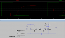
Anyway I may have found a better solution.
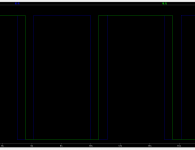
Please take a look at this sim where I have a bjt delay and also a 555 delay for comparison.
Attachments
you can use the 555 to delay the trigger signal.
You don't need all the extra delay circuitry for the middle relay.
But it might be worth adding in a "loss of mains AC and instant off" This is shown as an add on in the nab speaker prot.
I think it better to use a switching transistor between 555 OUT and the relay coil.
This allows you to use any of the low current 555 (mosfet type) and duals without having any dissipation concerns.
First don't use an inductor to emulate a relais, rather a resistance, an inductor has 0 ohm = shortcircuit.
In this case the 555 isn't a good choice, better use a 4013.
Something like this,mute time more or less 1/2sec.
Mona
Thank you Mona
I will study your circuit also.
PS: In my sim I set the coil series resistance to 1028ohms
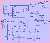
After much thought I decided to use three 555 timers to do the following:
U1 is used as a trigger to fire U3
So every time I touch the push button S3, U3 changes state (with a delay)
U2 is a timed monostable that acts as a mute and it is activated by push button S2
The circuit works perfectly as long as both push buttons S2 and S3 are actuated at the same precise moment.
The issue is that I found the double circuit push buttons I am using are not very precise so there is a lag between S2 and S3 closing circuits.
I need a circuit to replace S2 and S3 so I can actuate both U1 and U2 at the same time using only one push button.
Any advise will be most welcome as I am really running out of ideas.
Attachments
I am having trouble with windows 8......
I can read that very easily. Thanks.
you are using two 555 with 2 connected to 6.
and u2 with 7 connected to 6
Could you use one device to trigger both u1 and u2 with the same output signal?
two 556 gives you the extra device.
Is u1 driving u3 so that you have a defined delay?
Last edited:
- Status
- This old topic is closed. If you want to reopen this topic, contact a moderator using the "Report Post" button.
- Home
- Amplifiers
- Power Supplies
- Input switch / Mute delay using 555