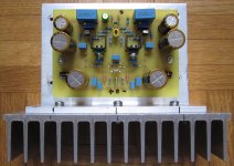
My VSSA build (PMI-like pcb) is not performing as expected. The sound is a bit distorted and the power output is rather low. I have set the output offset at 0.5mV and VAS bias at 14mA as recommended. I have not checked output bias. Test voltage is +/-33V. Inputs (BC550C-560C) and VAS (2SA1360/2SC3423) have been carefully Hfe matched (<5%). Outputs are 2SK1058/2SJ162. My low cob VAS transistors differ from the recommended KSA1381/KSC3503 because I could not match these (~50% difference). Does anyone have suggestions ?
Thanks.
Jacques
Thanks.
Jacques
Attachments
Last edited:
From a single photo it will be rather difficult to tell what might be wrong with your build. How do you know the bias value, if you didn't check it? Double checked all connections and parts values?
Zero (or wery low) bias can cause distortion, specially at low volumes.
Try to post a schematic with actual voltage values indicated on it.
Zero (or wery low) bias can cause distortion, specially at low volumes.
Try to post a schematic with actual voltage values indicated on it.
Last edited:
Afraid of something? VSSA is so trivial, anyone with basic knowledge of electronics can set-up properly. Now's the time to learn something by yourself, don't stop till it's fixed.I have not checked output bias.
Some have found the bias provided by two diodes is not enough and have had to add one or more diodes to the bias string. This is one reason I chose to use a Vbe multiplier on my boards and even LC himself used an adjustable shunt reference.
Ensure you have at least 120mA being drawn by the module to ensure enough bias.
EDIT: Also verify you feedback network values, a few builders have had a serious issues with feedback values, both mismatched between halves and overall gain set wrong.
Ensure you have at least 120mA being drawn by the module to ensure enough bias.
EDIT: Also verify you feedback network values, a few builders have had a serious issues with feedback values, both mismatched between halves and overall gain set wrong.
Last edited:
Afraid of something? VSSA is so trivial, anyone with basic knowledge of electronics can set-up properly. Now's the time to learn something by yourself, don't stop till it's fixed.
The bias value reported above was actually measured across the 10R VAS resistor (I obtained 140mV). Nothing wrong there. What I meant is that I did not measure total idle current.
I have fixed the distortion problem (bad DAC setting!). Gain is still a bit low: I wonder how much input is required for nominal output?
Soundwise, bass response is very good but treeble is a bit lacking as compared to my reference P3A amp. Might it be due the bipolar 4.7uF input cond?
Last edited:
Also verify you feedback network values, a few builders have had a serious issues with feedback values, both mismatched between halves and overall gain set wrong.
I have used 100R and 2.21K 0.1% precision resistors (Mouser 15 ppm).
Measuring voltage on the 10R VAS resistor will tell you close to nothing about the actual Io on the FET-s, because it is Vgs related, and the usual spread on those devices can result in anything between zero, and a few hundred mA-s (corresponding to the 140mV on the 10 ohm resistor) To find out the actual Io value, insert a 0.1R 2W resistor the between the supply line, and the drain of the Mosfet, and measure it there.
I also found that this amp -and in fact most CF topologies- sound excellent in the bass and mid region, but a bit shy (don't want to say lifeless, so -a bit too polite) on the top registers.
I'm not sure that the input cap will improve much on this, for some reason this is a feature of this type of design, I think..
Last edited:
Measuring voltage on the 10R VAS resistor will tell you close to nothing about the actual Io on the FET-s, because it is Vgs related, and the usual spread on those devices can result in anything between zero, and a few hundred mA-s (corresponding to the 140mV on the 10 ohm resistor) To find out the actual Io value, insert a 0.1R 2W resistor the between the supply line, and the drain of the Mosfet, and measure it there.
I also found that this amp -and in fact most CF topologies- sound excellent in the bass and mid region, but a bit shy (don't want to say lifeless, so -a bit too polite) on the top registers.
I'm not sure that the input cap will improve much on this, for some reason this is a feature of this type of design, I think..
I figured that the 10R VAS bias setup procedure recommended by PMI was a bit odd. What ideal value would you recommend by measuring across the additional 0.1R ?
People say that the FB capacitors need substantial burning in... Do you think additional treeble might show up later on ?
Io= Voltage measured across 0.1R/ Resistor value (0.1R). So 10mV across 0.1R means 100mA idle current.
If your OP Mosfets are 2SK1056-58, and 2SJ160-162 (I guess), their optimal Io value is around 150mA (15mV on 0.1R) that's where they are thermally most stable.
Feedback resistor burn-in?
Hmm.... better not say anything on that. There are parts what MIGHT sound better after a certain operating time (tubes, electrolytic caps, some film caps, speaker drivers, even some cables), but resistors? Don't think so.
But even if it is true, dont expect much improvement in the top bands. That is not part related in this case, but an inherent feature of this topology. (Saying this after building, and listening a few dozen different DIY and factory made amps)
One more thing: did you bypass the 1mF electrolytics in the feedback network? (the ones going from the 15k -100ohm junction to ground) If not, try to do so with something like a 1uf polyprop cap.
Last edited:
One more thing: did you bypass the 1mF electrolytics in the feedback network? (the ones going from the 15k -100ohm junction to ground) If not, try to do so with something like a 1uf polyprop cap.
I have 2200uF Nichicon FG there which I was told require some burning in (not the resistors, of course !) bypassed by 10uF film capacitors.

VSSA made properly can sing way lot better - four parts modification needed. Cardbox will miss it.. PM sent.I hope the VSSA will not end up in the old cardboard box full of single channel test builds...
")
Are we missing something?VSSA made properly can sing way lot better - four parts modification needed. Cardbox will miss it.. PM sent.

Actually not, we are all in expectations what Jacques will have to say later on.Are we missing something?
Wait, wait, maybe L.C. was just hallucinating.Yeah!..... We want mod !!

Lazy Cat is right !
Wow, with 5 mods (actually only 3 because of symmetry), you can turn this schematics into a winner.
With no doubt, one of the best sounding amps I have built so far.
Final evaluation will be done with two modded VSSA channels running, very soon.
It will be a Christmas gift to myself !
 Thanks again LC!
Jacques
Wow, with 5 mods (actually only 3 because of symmetry), you can turn this schematics into a winner.
With no doubt, one of the best sounding amps I have built so far.
Final evaluation will be done with two modded VSSA channels running, very soon.
It will be a Christmas gift to myself !
Thanks again LC!Jacques

- Status
- This old topic is closed. If you want to reopen this topic, contact a moderator using the "Report Post" button.
- Home
- Amplifiers
- Solid State
- My VSSA not performing as expected