Why so? On paper they seems similar to TF0410
Everything about it screams cheap made in China. The cone is thin and undamped, the metal for the frame could be pushed in with my bare hands, the glue around the magnet and back plate was slopped all over the place. It is nothing like the TF0410. Saying that the TF0615MR is just like a TF0410 but just a different size is like saying a Porsche 918 Spyder is just like a Boxster but just a different size.
Back at it!
Hey guys
So I finaly got around to fiddling with my 2-way Synergy horn SH95 clone employing the Faital HF146 along with twice Faital 8 FE200.
Here's what I don't get in relation to the Synergy patent:
You must not cross any lower then the flare rate dictates
With 90x55 this translates to CD flare rate ¨1250Hz
- Looks as if the B&Cs 8 NDL are crossed way lower then this, my guess is ~900Hz
Another thing that I can't wrap my head around is the flare rate of the mids:
700Hz (a~192cm) which translates into a flare rate of ~475Hz
Apparently this means that the SH95 doesn't follow the Synergy patent at all, that is, the mids doesn't really benefit from horn loading below 475Hz
I've been trying to follow the Synergy guidelines stricktly but I'm confused
Attachments
So I finaly got around to fiddling with my 2-way Synergy horn SH95 clone employing the Faital HF146 along with twice Faital 8 FE200.
At the risk of going dangerously of topic:
So, having read most of this thread, and tried a couple of things which didn't work out too well, I was lucky enough to pick up a pair of ex-rental SH95s for a reasonable price. They now grace my living room, twinned with a pair large home made scoops with 15 inch drivers.
The results are tremendous. The SH95s go incredibly loud on a tiny amount of input power. Imaging is great, and some 80s synth pop sounds radically different as you can hear all those angular waveforms from analog synths - Tom's claim of accurate square wave reproduction stands up, I'd say, and all those lovely harmonics come through.
So to my somewhat off topic question: I'd like to build some smaller (and frankly less ugly) subs to pair off with the SH95s. Any consensus on the way to go? I'm guessing some kind of tapped horn design but am somewhat lost as to where to start. My current scoops are about 4ftx2ftx2ft and don't have a very high waf.
Any hints gratefully received!
Nick,So to my somewhat off topic question: I'd like to build some smaller (and frankly less ugly) subs to pair off with the SH95s. Any consensus on the way to go? I'm guessing some kind of tapped horn design but am somewhat lost as to where to start. My current scoops are about 4ftx2ftx2ft and don't have a very high waf.
Any hints gratefully received!
If you want to go smaller and still reach 35 Hz, the Pal12 is a possibility.
http://www.diyaudio.com/forums/subwoofers/232219-325-lab-12-based-pa-tapped-horn-35hz-extension.html
If you want something equivalent to the DSL TH-18, XOCTH18 is the one.
http://www.diyaudio.com/forums/subwoofers/190635-th-18-flat-35hz-xoc1s-design.html
At about the same size, but perhaps with more WAF factor you could try the Keystone.
http://www.diyaudio.com/forums/subwoofers/185588-keystone-sub-using-18-15-12-inch-speakers.html
And yes, questions about subs are totally off topic in this thread.
Art
Last edited:
Synergy Bass Section
Hey Guys,
So I’m trying to get back in the Synergy horn saddle, but I need your help.
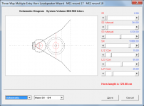
It’s about the bass section in a 3-way design:
It´s a 6th order band-pass. How do you determine front and rear chamber volume, port area and length – by trial and error?
Hey Guys,
So I’m trying to get back in the Synergy horn saddle, but I need your help.
It’s about the bass section in a 3-way design:
It´s a 6th order band-pass. How do you determine front and rear chamber volume, port area and length – by trial and error?
Thank you for asking this question!
I had just sent out a PM to a person I know that has built a few 3-way Synergy horns asking this same question. I would enjoy some feedback on the subject of designing the bass section of my Synergy horn. I had assumed it would be something similar to 6th order bandpass.
I had just sent out a PM to a person I know that has built a few 3-way Synergy horns asking this same question. I would enjoy some feedback on the subject of designing the bass section of my Synergy horn. I had assumed it would be something similar to 6th order bandpass.
Use Hornresp to model, it can include all the features of offset (Synergy style) horns as well as the bass reflex aspects.If you model a "regular" 6th order band-pass it seems that the front chamber volume turns out much to big....
Use Hornresp to model, it can include all the features of offset (Synergy style) horns as well as the bass reflex aspects.
Thanks Art,
I know hornresp, but I normally model in Akabak, as it's more acourate when it comes to port velocity?
- But what you are saying is that modeling is done by trial and error and not by following the general design guidelines of 6th order band-pass?
I use Akabak to model the entire synergy. The bass injection is not really horn loaded it just enters the periphery of the mouth walls and provides spatial summation to a point source. Modeling it is sort of a practical exercise for me. You look at how much room you have on the walls and that determines the size and number of woofers you can use. The more the better. Then based on cost constraints and the size constraint pick the woofer. Typically some high sensitivity PA style woofer for vented alignments. Then pick the size of the bandpass injection aperture (big is better for increased upper bandwidth) but too big and it reduces horn's directivity and efficiency. Typically you will end up with a hole with Sd of order 15% or so maybe 20% of cone Sd. Measure the volume between cone and horn wall and now you have everything you need to simulate in Akabak. That is the starting point. Then tweak aperture CSA and cone volume to get what you need (upper bandwidth) and minimize band pass overshoot hump. Play with position of hole for time alignment BR that is minor. Once the sim looks good see how you can reduce the volume with a speaker volume filler plug. Make the actual hole match the predicted Sd that was best. Install the drivers and test. You won't get much more than a few dB of gain from band pass injection and the mild horn wall directing it all forward. There will be gain from using 4 drivers if wires series parallel. So four 100dB woofers will now be 106dB and a good match for the mids and CD.
1) I'll take your word for itThanks Art,
1)I know hornresp, but I normally model in Akabak, as it's more acourate when it comes to port velocity?
2) But what you are saying is that modeling is done by trial and error and not by following the general design guidelines of 6th order band-pass?
.2) Modeling a horn driven by multiple offset drivers at various entry points is an iterative process that does not fit the "general design guidelines" (whatever they are) of 6th order band-pass particularly well.
XRK's post #1937 tells it like it is, although another consideration is the typical location of the BR ports puts them at the end of a reverse taper, which affects Fb quite a bit compared to the Fb if the ports were in a typical rectangular box.
Art
Thanks, xrk, Art.
Well I sort of would have hoped it was a little more like, start here - end there. But on the other hand I have been simulating the mids 4th order by trial and error, so I guees I will be doing the same for the bass section.
i actually already have the drivers for a SH-95 clone with Faital HF146 and dual 8FE200, but I though it would be more fun doing a full 3-way
Fun...i actually already have the drivers for a SH-95 clone with Faital HF146 and dual 8FE200, but I though it would be more fun doing a full 3-way
With the Faital 8FE200's 80 Hz Fs, using the bass reflex output you should be able to get a Fb in the 80-100 Hz range, at which point co-location of the sub woofers is not required for good imaging, and the subs can be placed for optimum room response.
I know hornresp, but I normally model in Akabak, as it's more acourate when it comes to port velocity?
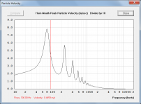
In my experience Hornresp and AkAbak port tube volume velocities (and therefore particle velocities) are identical, provided that end correction assumptions are similar.
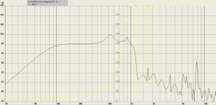
Attachment 1 shows AkAbak volume velocity where cross-sectional area = 0.035 m2.
At 100 Hz:
Volume velocity = 15.6 * 10 ^-3 m3/s
Particle velocity = volume velocity / cross-sectional area
Particle velocity = 15.6 * 10 ^-3 / 0.035 m/s
Particle velocity = 0.4457 m/s
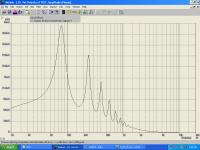
Attachment 2 shows the equivalent Hornresp particle velocity result.
The 0.0002 difference is due to the 15.6 coefficient in the Akabak volume velocity value being rounded to one decimal place.
Attachments
Use Hornresp to model, it can include all the features of offset (Synergy style) horns as well as the bass reflex aspects.
Attachments
I know hornresp, but I normally model in Akabak, as it's more acourate when it comes to port velocity
How are you measuring the port tube air particle velocity, to be able to say whether a simulation prediction is accurate or not?
Are you measuring at the port tube inlet, or the port tube outlet?
How are you measuring the port tube air particle velocity, to be able to say whether a simulation prediction is accurate or not?
Are you measuring at the port tube inlet, or the port tube outlet?
Hi David,
Thank you for your input.
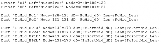
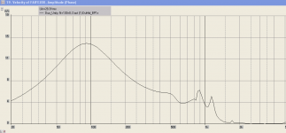
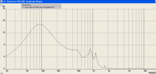
That's a good question. Attached is script and port velocity sims at node 130 and 170. They show identical velocity, Am I measuring at inlet an outlet?
Attachments
- Home
- Loudspeakers
- Multi-Way
- Suitable midrange cone, for bandpass mid in Unity horn.