Having tacked together a circuit and poking around to learn more about what it's doing, I was keen to check the results of the local plate to grid feedback (a la Schade) by measuring the effective Rp of the output tube. The circuit is a two stage direct coupled amp with plate to grid series R-C feedback on the output tube (triode), driven by a pentode.
I put a 10 ohm series resistor for current sense in the leg between output tube's plate and OT. Then with one RMS meter across that resistor for current and one RMS meter across the tube (P-K) for AC Vrms, I ran a 1K signal on the input (at several levels). Then took these two meter figures and calculated V/I for Rp. Easy Peasy ! Or at least it seems so. Am I overlooking anything here or is it really as simple as that? Thanks!
I put a 10 ohm series resistor for current sense in the leg between output tube's plate and OT. Then with one RMS meter across that resistor for current and one RMS meter across the tube (P-K) for AC Vrms, I ran a 1K signal on the input (at several levels). Then took these two meter figures and calculated V/I for Rp. Easy Peasy ! Or at least it seems so. Am I overlooking anything here or is it really as simple as that? Thanks!
Last edited:
Thanks for the reply. Sorry I didn't post a sketch but I was really asking about the method I used for measuring Rp. Not sure what danger you might be referring to. The HT? Are you suggesting taking the 10 Ohm out and putting 1R in the cathode as current sense , for safety in probing?
If you measure the output voltage from a stage with and without load you could say something about the output resistance (Ro) of the stage.
Ro = (V_noload – V_load) / (V_load/R_load)
Ro = Output resistance
V_noload = Voltage from the stage unloaded.
V_load = Voltage with load.
R_load = The load that you add to the stage.
Ro = (V_noload – V_load) / (V_load/R_load)
Ro = Output resistance
V_noload = Voltage from the stage unloaded.
V_load = Voltage with load.
R_load = The load that you add to the stage.
It is considered dangerous to have external test equipment hanging off not only an HT supply but through an inductor creating extremely high voltages. Do you remember the door bell at Science Class at school running on a 6Volt dry cell and producing enough back EMF from the coil to cause an electric shock? If one gets spikes enough for a shock at 6Volts, what do you think could happen at say 300Volts? Using a 1R (1 Ohm) in the cathode is almost at ground potential and will have little effect on the biasing conditions. Better be safe than sorry.Thanks for the reply. Sorry I didn't post a sketch but I was really asking about the method I used for measuring Rp. Not sure what danger you might be referring to. The HT? Are you suggesting taking the 10 Ohm out and putting 1R in the cathode as current sense , for safety in probing?
To measure a resistance you need to measure the voltage across it and the current through it, generated by a voltage/current source somewhere in the circuit. You (if I understand you correctly) were not doing this. Instead, you were measuring the voltage across the valve and the current through the valve, when the valve is the source of the current/voltage. Thus you are measuring the combined effect of the valve as signal source and the valve as impedance.
To measure the impedance of the valve you need to see how the voltage/current changes as the circuit impedance changes. Alternatively, drive in a signal from elsewhere.
To measure the impedance of the valve you need to see how the voltage/current changes as the circuit impedance changes. Alternatively, drive in a signal from elsewhere.
Wow, thanks for all the help!
I'm new to feedback and as I like Michael's approach to things in general I decided to start learning with his single supply M2 circuit.
I wanted to verify his statement that with the Schade feedback, the effective output impedance of the output triode (35TG listed rp ≈ 8500Ω) becomes either 400 or 500 Ohms, depending on the post quoted.
Though I didn't imagine it working/sounding well with a 5K OT unless the rp was lowered, I didn't know how or where the "effective rp" actually appears. Using the method in post #1 it tests as 570Ω.
Attachments
JUst a small note. It is accepted practice to use lower case letters for dynamic parameters such as you have been measuring i.e. rp.
Cheers IAn
I'd ignored that. Thanks.
If you measure the output voltage from a stage with and without load you could say something about the output resistance (Ro) of the stage.
Ro = (V_noload – V_load) / (V_load/R_load)
Ro = Output resistance
V_noload = Voltage from the stage unloaded.
V_load = Voltage with load.
R_load = The load that you add to the stage.
In the case of the sketched circuit how do I find V_noload ?
It is considered dangerous to have external test equipment hanging off not only an HT supply but through an inductor creating extremely high voltages. Do you remember the door bell at Science Class at school running on a 6Volt dry cell and producing enough back EMF from the coil to cause an electric shock? If one gets spikes enough for a shock at 6Volts, what do you think could happen at say 300Volts? Using a 1R (1 Ohm) in the cathode is almost at ground potential and will have little effect on the biasing conditions. Better be safe than sorry.
OK, that makes sense and I get it. Thanks.
To measure a resistance you need to measure the voltage across it and the current through it, generated by a voltage/current source somewhere in the circuit. You (if I understand you correctly) were not doing this. Instead, you were measuring the voltage across the valve and the current through the valve, when the valve is the source of the current/voltage. Thus you are measuring the combined effect of the valve as signal source and the valve as impedance.
To measure the impedance of the valve you need to see how the voltage/current changes as the circuit impedance changes. Alternatively, drive in a signal from elsewhere.
The 1K signal I put in was at the input to the driver pentode's G1 (RCA in). Is that what you mean by elsewhere?
Thanks
No. Your diagram confirms that you have not measured rp.Hearinspace said:The 1K signal I put in was at the input to the driver pentode's G1 (RCA in). Is that what you mean by elsewhere?
By "elsewhere" I mean almost anywhere which does not put a signal on the output valve grid. Put a signal on the grid and you are measuring the combination of a voltage source and a resistance and whatever other resistance is attached to it.
You could try injecting a signal at the output terminals, for example. However the difficulty you will have is that you need a load connected to keep the OPT safe, but the load may affect what you measure. If you know exactly what the OPT ratio is then you could perform load tests at the output and calculate rp from this.
Right, by definition it's with the grid voltage held constant. I'd let my limited view of the circuit input as input and output as output define my approach to testing and alter my view of the basics. Bad thinking. Thanks!
I can put the signal across the secondary and measure for V/I but would like to learn how to do the load tests you mentioned. Can you tell me how to go about it?
I can put the signal across the secondary and measure for V/I but would like to learn how to do the load tests you mentioned. Can you tell me how to go about it?
I've done some measurements but the results are not quite what I expected so I'd like to recheck methodology.
I put the disconnected output transformer on a variac and took measurements of primary and secondary at a few different input voltages. (100,80,60, 50, 25). The results gave a turns ratio of 33:1 - unexpected because the Transcendar TT-119-OT is spec'd at 5K:1 which translates to 25:1.
Next was to reconnect the OT and feed the amplifier under test a 1K signal at the input and set for 1Vrms at the open OT secondary. Then , begin loading the secondary with a pot until the output measures down 6dB (.5Vrms)
That done, the loading pot is disconnected and DCR measured and, added to that figure the secondary DCR.
Using the 1089 impedance ratio derived from the turns measurement >
1089 x 4.8Ω = 5227
Subtract Primary DCR of 295
5227 - 295 = 4932
So output triode z appears to be 4932. Not a crazy figure for the tube but it's a lot higher than the suggested 400-500.
Where am I getting this wrong?
Thanks
You need to subtract the secondary DC resistance. Did you add it?Hearinspace said:That done, the loading pot is disconnected and DCR measured and, added to that figure the secondary DCR.
However, this will only make a small adjustment. Has the feedback become disconnected?
Is the turns ratio measured with the 8R or the 4R tap? The output impedance is usually measured with the ON-OFF method. Take a reading with the secondary open, and another reading with it loaded, both using the correct tap. Then rout = (eo - el) x RL / el, where eo is the open circuit output voltage, el is the output voltage with load, and RL is the load value.
You need to subtract the secondary DC resistance. Did you add it?
However, this will only make a small adjustment. Has the feedback become disconnected?
Yes, you're right, I added it. Subtracting the .9Ω dcr makes the result 1.8 x 1089 smaller so that's not insignificant. (1.7 x 1089 = 1851Ω)
I didn't disconnect the feedback as my original intent was really only to verify Michael's statement that with feedback the resulting effective rp would be something between 400-500 Ohms.
I suppose all this would be easier too if I better understood how to work out the percentage of feedback from his schematic. Looking only at the voltages measured across the two sense resistors (one in series with Rfdb and one in series with the OT), it looks like roughly 10% but this is a pin the tail sort of guess on my part.
Also DF, I have to say thanks for sticking with this. It's helping me a lot and looking at the number of views, I'd say I'm not the only one interested.
I don't know how complete is the circuit you showed in post 8, but as it stands it would be quite difficult to calculate the output impedance. The 50k feedback resistor sends current back to a high impedance point, where you have the pentode anode plus active load plus 220k in parallel. The effective impedance there will be sample dependent, but will have an upper limit of 220k.
You would then have, in effect, an 'inverting opamp' type circuit with voltage gain around 50/220. This means that the voltage swing at the pentode anode will be much greater than at the output anode - the output stage is a voltage attenuator, but also current amplifier.
The likely outcome for output impedance is that it will be low, but rather nonlinear as the feedback ratio depends on things like the pentode anode impedance. A difficult circuit to analyse! You would need to see how the original designer analysed it, and check if his argument holds water.
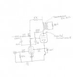
The open wire at the top is B+ of 600V, and the one at left of the 220K is a bias supply. Other than that and the missing power supply it's complete.
It's above my current level of understanding to do an analysis worthy of the name and as far as I know the designer, Michael Koster has fresher fish to fry.
I'm inclined to try again your earlier suggestion of injecting the signal at the output. Last week I started this with a signal generator but powering up the 35T's filament alone saw the input signal become badly distorted, I believe because the generator can't supply the current to drive the secondary. I'll try again with more current capability. More later. and thanks again!
I have had another think about the circuit. Given a high degree of feedback, you might expect to see an anode impedance in the region of 1/gm. If you are not seeing this then maybe the pentode active load is not as high an impedance as you expect?
I believe Michael Koster is sometimes around this forum.
I believe Michael Koster is sometimes around this forum.
- Status
- This old topic is closed. If you want to reopen this topic, contact a moderator using the "Report Post" button.
- Home
- Amplifiers
- Tubes / Valves
- Measuring Rp on the bench