Hi all.
I have been looking at composite amplifiers for some time (mainly due to Toms Modulus thread, but also bits I have found throughout the net.
I am looking to design something myself, and in all likelihood it will be a simple affair (to start) mainly as this would be my first composite design, based upon the boosted op amp topology.
I have read a few good references (Jungs Boosted Op amp paper, and a couple of others which seem relevant - titles escape me right now)
I am aiming for low THD, 10-20watts, and I will be initially just trying an op amp with voltage follower output stage, supplies limited to +/-20V depending on the op amp (unless I use separate rails for each stage) the rest is fairly mutable.
I have a few points I feel I need advice/further reference to clarify in my mind:
1) i realise that by buffering an opamp, and using the same rail voltages for the output stage, that power output will be limited.
Does anyone have advice in this regard? Is it beneficial to use separate rails for the OP stage? ( supply sag/modulation by the OP stage pops into my mind, but is there anything else?
2) I can simulate circuits (with a lot of effort), so perhaps stupidly, I prefer the build and improve process (not that simulation isn't of benefit, or something I refuse to do)
I realise that PM of each stage and the resulting PM is perhaps an issue inmay face - is simulation the only way if I can predict if i have resultant excess PM, and tendency to oscillate?
3) If I come up with anything decent, is there a soul generous and interested enough to test the design?
4) I welcome any comments, further references I may not have read, absolutely any advice, before I start?
Like i think Ive said, id like to largely learn and build something reasonable, with the least help from others here, but I am sure I will run into problems")
Thanks for reading, and for anything you may have to say on what I have missed (bound to be something)
I have been looking at composite amplifiers for some time (mainly due to Toms Modulus thread, but also bits I have found throughout the net.
I am looking to design something myself, and in all likelihood it will be a simple affair (to start) mainly as this would be my first composite design, based upon the boosted op amp topology.
I have read a few good references (Jungs Boosted Op amp paper, and a couple of others which seem relevant - titles escape me right now)
I am aiming for low THD, 10-20watts, and I will be initially just trying an op amp with voltage follower output stage, supplies limited to +/-20V depending on the op amp (unless I use separate rails for each stage) the rest is fairly mutable.
I have a few points I feel I need advice/further reference to clarify in my mind:
1) i realise that by buffering an opamp, and using the same rail voltages for the output stage, that power output will be limited.
Does anyone have advice in this regard? Is it beneficial to use separate rails for the OP stage? ( supply sag/modulation by the OP stage pops into my mind, but is there anything else?
2) I can simulate circuits (with a lot of effort), so perhaps stupidly, I prefer the build and improve process (not that simulation isn't of benefit, or something I refuse to do)
I realise that PM of each stage and the resulting PM is perhaps an issue inmay face - is simulation the only way if I can predict if i have resultant excess PM, and tendency to oscillate?
3) If I come up with anything decent, is there a soul generous and interested enough to test the design?
4) I welcome any comments, further references I may not have read, absolutely any advice, before I start?
Like i think Ive said, id like to largely learn and build something reasonable, with the least help from others here, but I am sure I will run into problems
Thanks for reading, and for anything you may have to say on what I have missed (bound to be something)
Well. I do happen to know a thing or two about composite amp design, so I figured I should chime in.
In a high-power amp, the main challenge is that the output stage will likely have much lower bandwidth than the controlling opamp. That's the main stability challenge. In addition, the characteristics of most high-power amps, such as the LM3886, change as the output voltage approaches the power rails. The power amp are also, generally, slower (lower slew-rate) than the controlling opamps. Hence, with a power IC, the stability challenge is three-fold:
Aiming for a low-power design can simplify the design greatly, as you have quite a few buffer ICs available. The LME49600 springs to mind. ADI has one that, supposedly, can provide quite a bit of current, assuming you can keep it cool. What these chips have in common is that they have much higher bandwidth (50-100 MHz) than power amps, such as the LM3886. If the bandwidth of the output stage is greater than that of the controlling opamp, the stability challenge becomes much more manageable.
10-15 W composite amp. Sounds like a fun project.
Tom
In a high-power amp, the main challenge is that the output stage will likely have much lower bandwidth than the controlling opamp. That's the main stability challenge. In addition, the characteristics of most high-power amps, such as the LM3886, change as the output voltage approaches the power rails. The power amp are also, generally, slower (lower slew-rate) than the controlling opamps. Hence, with a power IC, the stability challenge is three-fold:
- Stability with output near 0 V
- Stability with Vout near VCC or VEE
- Stability when output stage is slewing and controlling opamp is not
Aiming for a low-power design can simplify the design greatly, as you have quite a few buffer ICs available. The LME49600 springs to mind. ADI has one that, supposedly, can provide quite a bit of current, assuming you can keep it cool. What these chips have in common is that they have much higher bandwidth (50-100 MHz) than power amps, such as the LM3886. If the bandwidth of the output stage is greater than that of the controlling opamp, the stability challenge becomes much more manageable.
10-15 W composite amp. Sounds like a fun project.
Tom
Hi,
An interesting option originally used in the Texan design and
more recently reused by Rega in its original Brio design, is
to combine an op-amp, with a CFP output stage that has
some gain, and higher voltage rails than the op-amp.
rgds, sreten.
As usual, few words written; but fewer words wasted
Thanks
Well. I do happen to know a thing or two about composite amp design, so I figured I should chime in.
In a high-power amp, the main challenge is that the output stage will likely have much lower bandwidth than the controlling opamp. That's the main stability challenge. In addition, the characteristics of most high-power amps, such as the LM3886, change as the output voltage approaches the power rails. The power amp are also, generally, slower (lower slew-rate) than the controlling opamps. Hence, with a power IC, the stability challenge is three-fold:
Meeting these requirements and maintaining high performance was the main challenge in the Modulus-86 design.
- Stability with output near 0 V
- Stability with Vout near VCC or VEE
- Stability when output stage is slewing and controlling opamp is not
Aiming for a low-power design can simplify the design greatly, as you have quite a few buffer ICs available. The LME49600 springs to mind. ADI has one that, supposedly, can provide quite a bit of current, assuming you can keep it cool. What these chips have in common is that they have much higher bandwidth (50-100 MHz) than power amps, such as the LM3886. If the bandwidth of the output stage is greater than that of the controlling opamp, the stability challenge becomes much more manageable.
10-15 W composite amp. Sounds like a fun project.
Tom
Thanks for the input Tom. I say the design is fairly mutable since I have small numbers of some buffers, ideas of others I should buy, and a discrete OP isn't out of the question, but I'm starting simple.
LM675,
LME49600,
BUF 634,
A couple of those predriver ICs (LME49810?)
There's an interesting LT buffer, I forget the PN though.
From what you say, stability would probably be more of an issue with the BUF634 and LM675.
Unless I pick an op amp with a lower slew rate? That may be tricky with the LM675 (maybe the simplest looking option from my perspective to achieve 10 watts or so.)
Hi,
Details of the Brio can be found here :
http://www.diyaudio.com/forums/solid-state/54448-rega-brio-one-channel-dead.html
Its very prosaic, TL072 and ancient output transistors,
but it does it job very well, I can attest to that.
It fixes all the Texan basic problems.
rgds, sreten.
I like TinaTi as a simulator.
An interesting option [...] is
to combine an op-amp, with a CFP output stage that has
some gain, and higher voltage rails than the op-amp.
I refer to that as "an opamp with big shoes".
That's not a bad way to go, although, it does lack some of the plug-n-play simplicity that comes with using an actual power amplifier IC or buffer for the output stage.A couple of those predriver ICs (LME49810?)
They can't provide much current, actually. They're intended for driving an output stage. A couple of LME49600s in parallel could be your ticket.
Unless I pick an op amp with a lower slew rate? That may be tricky with the LM675 (maybe the simplest looking option from my perspective to achieve 10 watts or so.)
You don't want the opamp to slew at audio frequencies, so there's the lower limit. I suggest narrowing the field down by looking at the output current needed and selecting your buffer candidates from that. Then start playing with the circuit in the simulator. If you have issues with slewing, they'll be obvious when you simulate the step response using a fast edge rate (say 1 ns rise time). Don't forget to run the step response at various voltage levels (so 100 mV step, 200 mV step, ... 1 V step, etc). You may find that the circuit works well with a low step but hits the slew-rate limitation with a higher step.
Tom
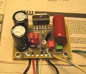
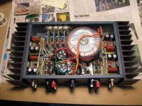
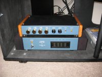
I built a 4 channel LM3886 poweramp and am very happy with it. Especially the no transient feature when you turn it on or off, so direct connection to a tweeter in a bi-amp arrangement is no problem (as it is with most other amps). It's about as simple as a power amp project gets. Phase margin/stability is an issue with any high gain negative feedback amp circuit. If your time is worth much, realize that you will be investing quite a bit of time into this, so build something that you will really appreciate for years to come. My 3886 amp delivers 50 watts rms into 8 ohms, with a +/- 32 volt power supply, which in my opinion is the least that I would want. You can squeak by on 10-20 watts if you never want to turn it up above "room volume" (just loud enough to hear everything well), or if you have very efficient speakers. Just remember that the reason low efficiency speaker drivers are so popular is because they sound better. Otherwise they wouldn't sell. There may be some rare exceptions to this, but there will be tradeoffs (such as price).
Attachments
Last edited:
A couple of LME49600s in parallel could be your ticket....
You don't want the opamp to slew at audio frequencies, so there's the lower limit.
selecting....
I suggest narrowing the field down by looking at the output current needed and selecting your buffer candidates from that...
I think calculated something like 6-7 LME49600 for a comfortable 70% dissipation or less, for 4 Ohms, if I recall.
As lower frequency limit comes into it (temporarily forgot about GBW) with the voltage gain and the 'lower' BW pole may end up close to the output device GBW as a buffer (say BUF634 or LM675)
Then start playing with the circuit in the simulator. If you have issues with slewing, they'll be obvious when you simulate the step response using a fast edge rate (say 1 ns rise time). Don't forget to run the step response at various voltage levels (so 100 mV step, 200 mV step, ... 1 V step, etc). You may find that the circuit works well with a low step but hits the slew-rate limitation with a higher step.
Tom
Thanks for the detail on the simulation Tom. Have to confess I have both TinaTI and LTspice but haven't gotten the hang of them much. Needs more time to get over the learning curve haha.
But id be quite capable checking with a sig gen and scope, sig gen would limit that to single digit Mhz (its old...), DSO is plenty fast enough (350Mhz), but only 8-bit.
Bob--lovely bit of kit, but that's a composite amplifier design without the composite. Was your point more to push north size-wise for future proofing? (If so, that's a very fair point).
Mondo--in my preliminary design work (on pause until I get proper phase margin info on my tda7293's), unless you design every possible compensation combination into your boards, you're really, really going to want to spend some serious time in SPICE.
Mondo--in my preliminary design work (on pause until I get proper phase margin info on my tda7293's), unless you design every possible compensation combination into your boards, you're really, really going to want to spend some serious time in SPICE.
I recommend CFA output op amps which can have gain (or be used unity gain to start if you don't yet understand the loop gain/compensation requirements)
some are made in power packages - LT1206/1210 in TO-220 are handy
smt "power pad" packages are bit more of a home builders soldering challenge
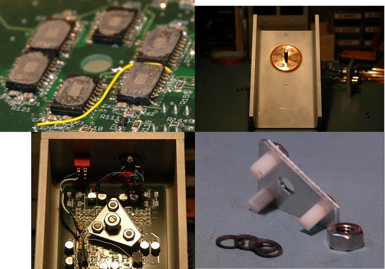
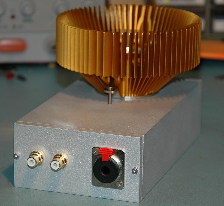
but also a opportunity for even more effective heat sinking with a little effort:
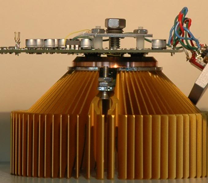
some are made in power packages - LT1206/1210 in TO-220 are handy
smt "power pad" packages are bit more of a home builders soldering challenge
but also a opportunity for even more effective heat sinking with a little effort:
6x TPA6120 dual op amps, rated 400 mA each op amp - parallel pairs biased against each other for Class A push-pull output (a little over 200 mA Class A bias for the headphone amp)
this is sized as a headphone amp so the outputs are cascaded for higher drive V (600 Ohm cans or the insanely low sensitivity AKG K1000)
TPA has exposed Cu power pad meant to be soldered to board for several W dissipation, by soldering "belly up" I contact them to the Cu slug of a pc cooler - running ~ 30 W quiescent total without fan
re arranging the I,V by flat paralleling you could get 2.4A, 15 V peak each channel for ~ 14 Wrms into 8 Ohms Class AB stereo
all up, both channels paralleled as a monoblock the shown components, heatsink should drive down to ~3 Ohms
I think calculated something like 6-7 LME49600 for a comfortable 70% dissipation or less, for 4 Ohms, if I recall.
That sounds about right.
Have to confess I have both TinaTI and LTspice but haven't gotten the hang of them much. Needs more time to get over the learning curve haha.
I tend to use LTspice for tube circuits and TINA-TI for solid state, simply because I usually use TI chips and the model support works with TINA. In some aspects, I find TINA-TI easier to use. In others, LTspice wins. Both are engineering software, so really quite quirky and non-intuitive. However, if you have lab experience, it shouldn't take too long to get going with either simulator once you're used to the terminology.
Simulations such as parametric sweeps allow you to sweep, say the resistance of a resistor, over a couple of orders of magnitude in a few seconds, whereas running that experiment in the lab would take the better part of a day.
Tom
Nice build there, jcx. Just be careful not to nick the bondwires when you sand down the package plastic.
Last I did something like that, I was using APEX high-voltage opamps with an exposed DAP. I put a bunch of thermal vias under the package and poured a plane on the bottom of the board. Tied this plane to a piece of aluminum that I milled for the purpose with a piece of SilPad sandwiched in between. It worked pretty well.
Tom
Last edited:
those are PowerPad(tm) packages mounted "belly up"
only had to bend the leads externally
http://www.ti.com/lit/an/slma002g/slma002g.pdf
reflow soldering to PCB with thermal vias and planes are the intended application but I wanted more - and eliminates the guesswork with home soldering the power pad
only had to bend the leads externally
http://www.ti.com/lit/an/slma002g/slma002g.pdf
reflow soldering to PCB with thermal vias and planes are the intended application but I wanted more - and eliminates the guesswork with home soldering the power pad
Last edited:
those are PowerPad(tm) packages mounted "belly up"
Arh. That makes more sense. I'm looking at upside down devices covered in thermal goop. I thought you'd sanded them down.
Not exactly a production flow, but for a one-off, who cares.
Tom
@JCX,
Yup the LT1210 was the buffer in question (but costly) as I also like the TO220 package for ease of mounting - and yes initially I was planning to try unity gain, with the intent to try 2-3 V/V when I have gotten a bit more of a handle on the changing requirement for compensation.
This is only a small amplifier for desktop use, so I guess 10-15W is plenty and I could probably manage with less (despite low efficiency drivers)
- Status
- This old topic is closed. If you want to reopen this topic, contact a moderator using the "Report Post" button.
- Home
- Amplifiers
- Chip Amps
- composite amplifier design: advice and thoughts before I start please.