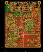
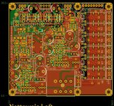
Keantoken's inspiring design of the Kuartlotron super buffer definitely deserves serious attention and more than one type of implementation") With this post I'm putting up a compact PCB layout, welcoming comments, opinions, ideas, and criticisms of course, hoping it can become something one can install in a chassis and enjoy in a living room or a study, not just on a test bench
With this post I'm putting up a compact PCB layout, welcoming comments, opinions, ideas, and criticisms of course, hoping it can become something one can install in a chassis and enjoy in a living room or a study, not just on a test bench
A few quick points about the implementation:
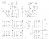
1. power supply: takes twin 12VAC winding secondary (not center-tapped) power transformer. LM317T as 1st stage regulator, low noise LT3065, LT3090 as 2nd stage regulators. Not only because these are small in size and cool to the touch, but the pulsing current at the rectifiers can be many times smaller than would with a hot regulator, likely less trouble to have to deal with.
2. Output delay/muting controlled by regulator's Power-Good signal, external muting can be easily line-OR-ed with the on-board Power-Good signal (I'll put in a 2-pin header for that.)
3. RK27 as default volume pot
4. Right hand side edge of the layout could be extended by 30mm to accommodate input selection relays. But I decided to leave it out for now, as there could be many different desired types of set-ups, component choices, and some compact chassis design may not have the needed room on the right hand side of the pot. However an off-board relay board of any kind, an improvised built perf-board for example, could be easily attached to the right hand side using right angle headers and socket --- we have the audio input and the -12V (for the relay coils) right at the edge. I could be doing another version that comes with the input selection relays too.
5. I like relays with 5mm pin spacing as it allows guarding ground traces wrapping around the signals.
6. I don't like SMD electrolytic caps as they can be knocked out by accident causing non-repairable damage to the PCB. Large and tall parts always through-hole for me. (sorry Jean-Paul)
With this post I'm putting up a compact PCB layout, welcoming comments, opinions, ideas, and criticisms of course, hoping it can become something one can install in a chassis and enjoy in a living room or a study, not just on a test benchA few quick points about the implementation:
1. power supply: takes twin 12VAC winding secondary (not center-tapped) power transformer. LM317T as 1st stage regulator, low noise LT3065, LT3090 as 2nd stage regulators. Not only because these are small in size and cool to the touch, but the pulsing current at the rectifiers can be many times smaller than would with a hot regulator, likely less trouble to have to deal with.
2. Output delay/muting controlled by regulator's Power-Good signal, external muting can be easily line-OR-ed with the on-board Power-Good signal (I'll put in a 2-pin header for that.)
3. RK27 as default volume pot
4. Right hand side edge of the layout could be extended by 30mm to accommodate input selection relays. But I decided to leave it out for now, as there could be many different desired types of set-ups, component choices, and some compact chassis design may not have the needed room on the right hand side of the pot. However an off-board relay board of any kind, an improvised built perf-board for example, could be easily attached to the right hand side using right angle headers and socket --- we have the audio input and the -12V (for the relay coils) right at the edge. I could be doing another version that comes with the input selection relays too.
5. I like relays with 5mm pin spacing as it allows guarding ground traces wrapping around the signals.
6. I don't like SMD electrolytic caps as they can be knocked out by accident causing non-repairable damage to the PCB. Large and tall parts always through-hole for me. (sorry Jean-Paul
)Attachments
Nattawa Hello!
This is a great layout but my eyes would not allow me to weld such small components.
All connections are checked because it is difficult to see like this?
Regard's!
Thanks, Project16. I'm not a young dude myself and I wear reading glasses when reading. I use magnifying glass myself when working on even through hole PCBs. I found it to be true that assembling SMD boards is not as straightforward as a through-hole PCB. But one can develop the skill quickly with proper tools and material, plus some patience. Naked eyesight itself perhaps isn't a real issue for most. It does take a bit learning and practicing.
To answer you question, yes, all connections in the layout have been checked 100% sync-ed with the schematic.
Nice work!
Is it on your plan to share this pcb?
Yes, I will share it. But only after I have done the first build and it has been proven working well, of course. If you or anyone are interested in building the first batch I wouldn't mind posting the Gerber and NC drill package.
Perhaps the way I put up the layout designs make them appear to be next to a finished final, and by that, sort of closed off the door and discouraged discussion? Or perhaps most are simply not wanting or ready to touch SMD?
I saw you made good progress with your layout and that was quite impressive. I think you really should proceed and finish it.
I saw you made good progress with your layout and that was quite impressive. I think you really should proceed and finish it.
But also I'd prefer a relay board with a little more space between relays and not as close to the main board. But that's me.
The layout in the first post would work with a separate relay board. I'm planning on a separate relay board design, hopefully including RCA jacks and push-button channel control on it.
For a compact all-in design shown in post #8, I try to have the board under 100 mm to keep the cost down. Parts might seem to be tightly packed, but do you see anything specifically that can go wrong?
Large and tall parts always through-hole for me. (sorry Jean-Paul
That's fine, I do the same. What a nice board you made and it seems usable in real life too. But why LM317 for negative when LM337 exists ? Also relay contacts are in the audio path when switching output to GND would keep them out of the path. Just some remarks, otherwise a fine board at first glance (will look in depth later). I would not use caps over the diodes, only snubbers (and Schottky diodes
)
Last edited:
That's fine, I do the same. What a nice board you made and it seems usable in real life too. But why LM317 for negative when LM337 exists ? Also relay contacts are in the audio path when switching output to GND would keep them out of the path. Just some remarks, otherwise a fine board at first glance (will look in depth later). I would not use caps over the diodes, only snubbers (and Schottky diodes
I didn't look close at the regulation. I'd prefer unregulated to basic LM3XX noise machines.
I'm sure JP is right about the relays. However ground noise is a real thing too. I like switches, instead of relays. But they're harder to make remote control so I haven't done it!
....Also relay contacts are in the audio path when switching output to GND would keep them out of the path. ....
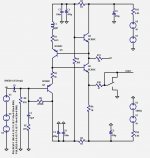
Thanks Jean-Paul for bringing the muting relay up. I did not give it much thought. Would you recommend a muting relay connection shown as the attached pic? If I connect it that way and when muting is activated, since the Kuartlotron buffer has a current sinking limit at about 8mA, the Q2 and Q4 would begin to cutoff when the input signal exceeds 0.45Vpk, decided by value of R10.
It seems to me to be ok to allow the transistors to cutoff as the signal is being muted anyway, and my simulation of transistor dynamic power dissipation indicated good safety margin against SOA. But I would appreciate your opinion about it. If needed I can increase R10 to allow a greater input level at muting without transistors going into cutoff. For example, making R10 150-ohm would allow 1.3Vpk at input and no cutoff, while the output impedance of the buffer is still reasonably low.
...But why LM317 for negative when LM337 exists ?
Is it bad to do a split supply using two LM317 the way I did? I use two LM317 only to reduce component variety so that I could buy one less part and reduce chance of error at the PCB assembling.
I would not use caps over the diodes, only snubbers (and Schottky diodes
Ok, Schottky diodes and snubers are the recipe.
Attachments
I didn't look close at the regulation. I'd prefer unregulated to basic LM3XX noise machines.
I'm sure JP is right about the relays. However ground noise is a real thing too. I like switches, instead of relays. But they're harder to make remote control so I haven't done it!
Thanks. What would you recommend as replacement to LM317 for the first stage regulators? If they are so bad that an unregulated would be superior it's quite easy to just jumper them out.
Well, it doesn't need DC protection on the way in. However equipment on the way out may. Also you can make one side a track instead of individual holes, for odd caps.
The cap at the input is not for protection against incoming DC, but for preventing the pot from trimming the buffer offset, although it happens to perform the DC blocking duty. I'll see how stable the output offset goes then decide on an output cap at Rev.2 layout. It's supposed to be unnecessary by the excellent thermal cancelling design and the use of matched dual transistors.
Hi,Wouldn't it be better to turn the muting relay around that it is in mute at power up?
The PCB was designed to have the relay at muting position at power up by reading the Power Good signal, as shown in schematic in post #1. The schematic in post #16 shows relay in non-muting position after power up.
Also, if let say 1V signal is at the output then the shorted to ground R10 (mute is ON) will conduct ~20mA. Is it OK for a preamp output?
The buffer is not capable of that much current as Q2 and Q4 would begin to cutoff when input exceeds 0.45Vpk, or 0.32Vrms. See post #16. Stimulations have indicated transistors are safe when output is shorted to ground.
- Status
- This old topic is closed. If you want to reopen this topic, contact a moderator using the "Report Post" button.
- Home
- Source & Line
- Analog Line Level
- Kuartlotron Preamp Implementation, SMD Heavy.