And overvoltage too
Also beware of overvoltage from power companies attempting to counteract the brownouts.
Another war story: when a startup company had a tradeshow appearance they got powered loudspeakers from a division of Harman. The person responsible for the design figured that amplifier chips used in automotive products would work well in the application, and of course everything was tested before shipment. At the show nothing worked! Frantic efforts were made to diagnose, backup equipment was sent---but all that was wrong was that the electricians at the hotel, weary of people complaining of too-low mains voltages at previous shows, jacked everything up! The automotive chips were expecting no more than an 18V power rail, which would be quite high for a car and a sign something was wrong. As there was no regulation inside the speakers, it was a fatal behavior. By the time the correct diagnosis was made and variacs shipped to reduce the mains inputs, it was about the end of the show, and the loss of face was terrible all round.
Hello everybody,
For a quick intro, I'm reminding I have a DIY USB DAC made from 16 parallel pieces of TDA1543 at 8.5V, powered by a BLB 1.1. The digital board is the JLSOUNDS XMOS asynchronous board with galvanic USB isolation that is powered by two BLB 1.1 boards at 5V. The boards from TeaBag.
The power supply before the regs consists of three choke input (LC) stages with separate transformers.
A few days ago at work, where we have a high-end audio system, I brought my DAC for a listen. It sounded promising, very musical, relaxed, natural, but a bit muddy. Well, the same muddiness, kind of a struggling feeling I had at home.
The next day, I was just finishing my two REFLEKTOR-D TeaBag boards, made with Dale resistors, aluminum polymer 1500uF 16V Vref bypass cap, russian mylar 100n for the Zobel and Panasonic FC 2200uF for the main filltering salvaged from my old Salas boards.
I removed the BLB 1.1 boards powering the XMOS board and put the configured REFLEKTOR D boards on their place. I soldered good Neotech single crystal copper wire, turned the on and listened for a few hours.
Honestly, I am impressed. The REFLEKTOR D seems to work much better, much of the muddiness is gone. The sound is more immediate, punchy, dynamic, entertaining and detailing, while it keeps the level of naturality without going harsh.
At the end of day, I realized that some of the slowness of the sound also comes from a non-adequate cooling of the TDA1543 chips and we found out that there is a "golden" temperature for them. Too cool and they sound a detailed, resolving, but sterile. Too warm and they sound constricted, confused, weird. The goal was to add heatsinks until we achieved a stable and good sounding temperature and it was at 45C.
Today I took from home with me two big cans - RIFA PEH169 1800uF 160V. For me, this PEH169 series is a no-compromise electrolytic capacitor, which beats even some non-electrolytic caps. It was first thinking where to try them, and then I realized it was easiest to change the main filtering cap. The original ones to remind you where PANASONIC FC. I desoldered these, I put the RIFAs near the board and used 10cm wires to connect them. I then turned on the DAC, took a sit to listen and... WAOW! We are listening to a different source, it seems? What happened to that smoothy one? Gone!
To summarize, I am sure every component on the board influences the sound, so I am just reminding how impressive it can be.
I also want to thank Salas again for his ingenious creations and all the good support and knowledge he gave to me and he still does to the other members!
P.S. I will continue my experimentation with various components on the boards. Maybe the next think will be a Mundorf supreme for the BLB 1.1 zobel . Or for the Vref?
For a quick intro, I'm reminding I have a DIY USB DAC made from 16 parallel pieces of TDA1543 at 8.5V, powered by a BLB 1.1. The digital board is the JLSOUNDS XMOS asynchronous board with galvanic USB isolation that is powered by two BLB 1.1 boards at 5V. The boards from TeaBag.
The power supply before the regs consists of three choke input (LC) stages with separate transformers.
A few days ago at work, where we have a high-end audio system, I brought my DAC for a listen. It sounded promising, very musical, relaxed, natural, but a bit muddy. Well, the same muddiness, kind of a struggling feeling I had at home.
The next day, I was just finishing my two REFLEKTOR-D TeaBag boards, made with Dale resistors, aluminum polymer 1500uF 16V Vref bypass cap, russian mylar 100n for the Zobel and Panasonic FC 2200uF for the main filltering salvaged from my old Salas boards.
I removed the BLB 1.1 boards powering the XMOS board and put the configured REFLEKTOR D boards on their place. I soldered good Neotech single crystal copper wire, turned the on and listened for a few hours.
Honestly, I am impressed. The REFLEKTOR D seems to work much better, much of the muddiness is gone. The sound is more immediate, punchy, dynamic, entertaining and detailing, while it keeps the level of naturality without going harsh.
At the end of day, I realized that some of the slowness of the sound also comes from a non-adequate cooling of the TDA1543 chips and we found out that there is a "golden" temperature for them. Too cool and they sound a detailed, resolving, but sterile. Too warm and they sound constricted, confused, weird. The goal was to add heatsinks until we achieved a stable and good sounding temperature and it was at 45C.
Today I took from home with me two big cans - RIFA PEH169 1800uF 160V. For me, this PEH169 series is a no-compromise electrolytic capacitor, which beats even some non-electrolytic caps. It was first thinking where to try them, and then I realized it was easiest to change the main filtering cap. The original ones to remind you where PANASONIC FC. I desoldered these, I put the RIFAs near the board and used 10cm wires to connect them. I then turned on the DAC, took a sit to listen and... WAOW! We are listening to a different source, it seems? What happened to that smoothy one? Gone!
To summarize, I am sure every component on the board influences the sound, so I am just reminding how impressive it can be.
I also want to thank Salas again for his ingenious creations and all the good support and knowledge he gave to me and he still does to the other members!
P.S. I will continue my experimentation with various components on the boards. Maybe the next think will be a Mundorf supreme for the BLB 1.1 zobel
. Or for the Vref?
Last edited:

The A1015's are as good if not bit more linear and noiseless.
Hi Salas,
I can not find 2N4403 here in Germany but lots of SA1015
Transistor 2SA 1015, Si-P, 50V, 0.15A, 0.4W 80mhz
are those ok?
Get the GR beta grade (the highest).Hi Salas,
I can not find 2N4403 here in Germany but lots of SA1015
Transistor 2SA 1015, Si-P, 50V, 0.15A, 0.4W 80mhz
are those ok?
Yes I use lots of SA1015. The rbb' is about the same as the 4403, which sets a lower limit to the voltage noise.
Get the GR beta grade (the highest).
Yes I use lots of SA1015. The rbb' is about the same as the 4403, which sets a lower limit to the voltage noise.
THX,
what about the MTP3055VL can I use TIP3055STM?
No, that's an NPN Transistor. You need a Logic Level (low Vgs threshold) MOSFET like the MTP3055VL is.
Thanks Salas,
The only Mosfet I can find that compares to MTP3055VL is BUK100-50GL. Would
this work?
Hi Guys!
This thread does not want to come to an and. Luckily!
I read it all, took almost a week but my knowledge is so improved I have headache!
It is not enough to congratulate with Salas, Iko and all who contributed to this thread to create something new and amazing.
Well, said this I am planning to employ Salas regulators in my ES9018-based DAC.
I read in some posts before that a japanese guy (sorry for forgetting his name now) has been able to obtain 1.2V out of it for the core voltage of the DAC. Despite his success I am a bit concerned on stability of a so low voltage. ES9018 datasheet specify a tolerance of +/- 5% on declared voltage. So the thresold is 1.14 to 1.26.
Salas cleverly said in an old post that in this case he would reduce the voltage to the required value with and RC filter (please Salas tell me if I did not understand your tought). Unfortunately the DAC supply current changes with the sample rate, clock frequency, and other variables you find in the DS. So, due to so strict tolerances, I see this approach difficult to be predictable. Maybe it is ok if you plan to run your DAC at a fixed sample rate etc. But it is not my case.
So my idea is to have a 3.3V output salas regulator (3.3V are required too by the ES9018) and then obtain 1.2V from this:
http://www.ti.com/lit/ds/symlink/tps74012.pdf
It displays a regulation accuracy of 2% that fits the application
unfortunately the datasheet tells nothing about noise figure.
Any tought?
Thanks!
Daniele
Last edited:
Hi Daniele, thanks.
Post reg LDO is a practical configuration indeed. Most DAC boards that ask for a general regulated line input of say 5V utilize several SMT post regs for different functions and voltage levels.
That one you linked curiously does not mention noise performance so we should at least presume its not falling in the low noise category. If availability in a manageable protruding pins package is what you are looking for among other things, then the ON Semiconductor NCP565ST12T3G is a chunky SOT-223 1.2V 1.5A 38uV Low Noise 2% accuracy guy available at Mouser in stock. Does not look half bad for your purposes. Fixed voltage, only couple of support components to apply. It should combine alright with a Reflektor-D at 3.3V since it will work correctly from 2.5V up to 9V input.
NCP565ST12T3G ON Semiconductor | Mouser
P.S. The RC step down solution was to address predictable current draw, or for small variation resulting within spec limits Vdrop, yes. I could extend that idea to silicon junction drops though. But not too precisely predictable for the % accuracy you are after. Much trial and error with real parts.
Klaus,
You talk the Ref-D board I presume. That board is roomy for all resistors, so you can use your favorite 0.6W types.
The reason for those specific parts choices mix is value for money regarding their good characteristics and availability in the American market as a steady BOM config. Its the parts the prototypes were tested and evaluated on also. Those choices are in no way restrictive.
Salas et. al-
Although I have read a good portion of this thread, I must admit that I have not made it through all 700 pages...
Is there a way to configure the original (or subsequent modified versions) for a very low output voltage? I have some DHTs that require 1.25V at 10mA and am in need of a good, quiet filament supply and thought this might be a good candidate.
Also, my SPICE simulations seem to suggest that the performance of the original circuit is better with IRF9640 as Q1 and IRFP9240 as Q2. Is there a reason for this?
Sorry for my lack of engineering prowess...
It tends to double register some posts in random today. Some server glitch probably.
The big MOSFETS have low RDS and high transconductance, I use them in the DCB1 since 2008 which uses a variation of the SSLV regs theme. But they tend to show their teeth better in HOT-ROD. I.e. burning much excess current above the client circuit's need.
You could use some chunky diodes in series to the regulator output and a 1000uF capacitor across the filament. Say 6 pieces so to drop about 4.2V and then tune the reg around 5.5V until the remaining difference across the filament is 1.25V. Because the MOSFETS have high VGS voltage much above 1.25V that won't allow such a low direct output.
Hi Salas et al,
nice to see that this thread is still active. Please forgive me for not making it through yet (arrived at p.16), but I've started out with shunt regs just yesterday. I got hooked somehow while reading through Stan Curtis' article in the latest Linear Audio Vol. 10 ...
I'd like to ask you a question. If it has already been answered in this thread, I'll probably find it someday, but I could not resist asking it now.
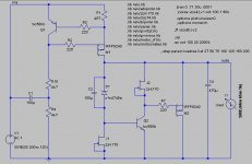
It is about the CCS made up of J1 in the circuit posted in #8 (attached here again for easy reference). Since it is paralleled by Q2's Base-Emitter junction, it should never have more than around 650mV of working voltage range, give or take a couple mV. According to a simulation in isolation, a CCS with any JFET needs at least 1V to be working properly, thus it will always be out of regulation, acting more or less like a simple resistor. The B-E-voltage will not rise above 1V under normal circumstances, so the question arises: Will a simple resistor in position of J1 be any/much worse than the CCS?
Things to consider: Does a JFET CCS in reality actually need more than 1V to regulate properly and hence the sim is actually predicting worse behavior here? Anybody made any actual measurements? Did anybody try this already or is willing to do it? I don't have any SK170's or something similar at hand, so I can't test it myself...
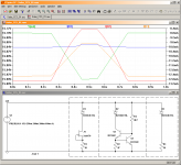
I tried to simulate three possible versions for a 15V zener and just over 16V output. The plot shows 16V output varied by 100mV in both directions and the corresponding change in zener current. The JFET clearly fares the best here and the bipolar CCS seems totally unusable with such low voltages. Except for allowing a higher current with greater voltage difference, the single resistor seems to keep up pretty well. It's advantages would be the cost savings and better possibility to adjust the current - it might be a trimpot, for instance.
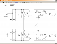
That's the one thing. Here's another thought: Since I'm planning on building a symmetrical version for 2x200mA, I could easily tie the CCS' to their opposite rails, together with, say, 1k each in line, for an increased voltage drop over the JFET so that it stays in proper regulation. Then it would also be possible to use a bipolar CCS instead, which seems to be a little more constant than the JFET (according to the simulator), and again could be more easily adjusted for desired/optimal current. You'll find a schematic of this idea attached. Unfortunately I couldn't figure out yet how you did those nice impedance plots...
Best regards,
Lasse
nice to see that this thread is still active. Please forgive me for not making it through yet (arrived at p.16), but I've started out with shunt regs just yesterday. I got hooked somehow while reading through Stan Curtis' article in the latest Linear Audio Vol. 10
...I'd like to ask you a question. If it has already been answered in this thread, I'll probably find it someday, but I could not resist asking it now.
It is about the CCS made up of J1 in the circuit posted in #8 (attached here again for easy reference). Since it is paralleled by Q2's Base-Emitter junction, it should never have more than around 650mV of working voltage range, give or take a couple mV. According to a simulation in isolation, a CCS with any JFET needs at least 1V to be working properly, thus it will always be out of regulation, acting more or less like a simple resistor. The B-E-voltage will not rise above 1V under normal circumstances, so the question arises: Will a simple resistor in position of J1 be any/much worse than the CCS?
Things to consider: Does a JFET CCS in reality actually need more than 1V to regulate properly and hence the sim is actually predicting worse behavior here? Anybody made any actual measurements? Did anybody try this already or is willing to do it? I don't have any SK170's or something similar at hand, so I can't test it myself...
I tried to simulate three possible versions for a 15V zener and just over 16V output. The plot shows 16V output varied by 100mV in both directions and the corresponding change in zener current. The JFET clearly fares the best here and the bipolar CCS seems totally unusable with such low voltages. Except for allowing a higher current with greater voltage difference, the single resistor seems to keep up pretty well. It's advantages would be the cost savings and better possibility to adjust the current - it might be a trimpot, for instance.
That's the one thing. Here's another thought: Since I'm planning on building a symmetrical version for 2x200mA, I could easily tie the CCS' to their opposite rails, together with, say, 1k each in line, for an increased voltage drop over the JFET so that it stays in proper regulation. Then it would also be possible to use a bipolar CCS instead, which seems to be a little more constant than the JFET (according to the simulator), and again could be more easily adjusted for desired/optimal current. You'll find a schematic of this idea attached. Unfortunately I couldn't figure out yet how you did those nice impedance plots...
Best regards,
Lasse
Attachments
Hi, please read posts 6831 - 6847 where J1 and its VDS impact has been discussed again fairly recently. In brief the JFET would do best with more voltage across indeed but holds better still than a simple resistor which is not that bad and if having no very low noise very low Vp J1 type, using a resistor won't break the deal.
Cross referenced CCSs among polarities we have not practically attempted.
Cross referenced CCSs among polarities we have not practically attempted.
- Status
- This old topic is closed. If you want to reopen this topic, contact a moderator using the "Report Post" button.
- Home
- Amplifiers
- Power Supplies
- The simplistic Salas low voltage shunt regulator