Hi all,
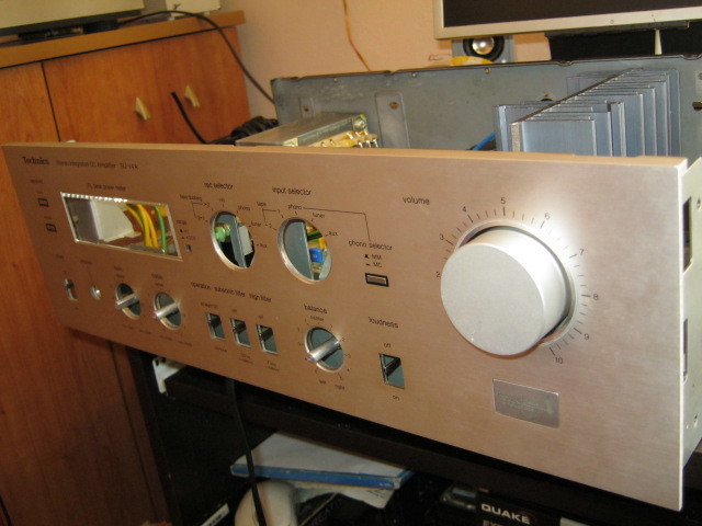
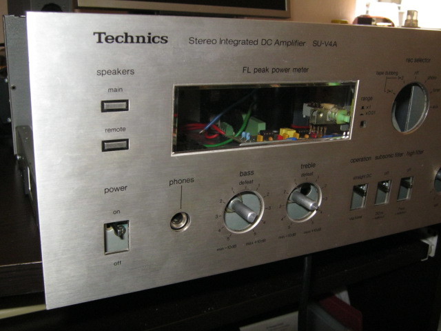
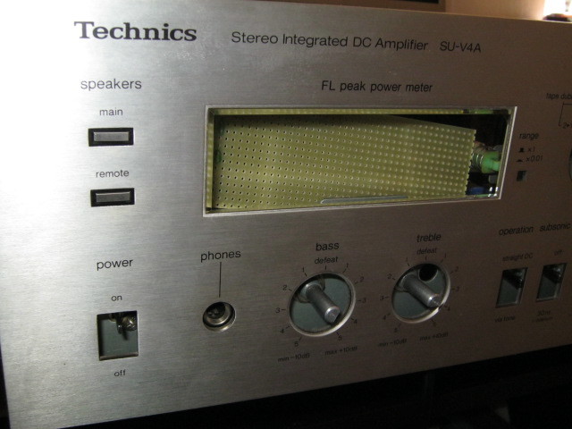
I have had a mission repairing an old Technics SUV4A amplifier and learnt a few handy tips along the way which I will share with you.
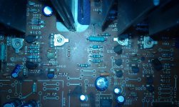
1/ If you need to replace the main amplifier ICs (a common fault in this amplifier - each one is an STK 8050), make absolutely sure that you first adjust both clamp voltage and idle current variable resistors to the full anticlockwise position. This is imperative as aftermarket STK8050s tend to operate at a much lower idle current and clamp voltage compared to the original ICs. If you don't do this before powering the amp up after fitting replacement ICs you will almost certainly blow both of them (I learnt this the hard way).
2. Follow the service manual to adjust clamp voltage on each channel (first ensuring R367 and R368 are turned full anticlockwise, along with R337 and R338) after 10 minutes warm up but DO NOT adjust it to 0.5mV!! Adjust it to about 0.1-0.2mV max. You will find that this is only a very small movement up from full anticlockwise on R337 and R338.
3. To adjust idle current, don't bother measuring the mV with a multimeter - just move R367 and R368 a tiny fraction up from full anticlockwise.
4. Carry out voltage tests on the legs of IC303 to confirm it is working correctly. This chip is known to fail on this amp.
5. Check resistor R326 for open circuit. This can also fail on the amp. On the amp I repaired, it had two blown STKs, a blown IC303 and a burnt out R326.
6. Check the volume control for signs of a worn track. The amp I repaired had a worn volume control which caused nasty voltage spikes and a crackling sound in the test speakers.
7. The input selector switch can become worn which can manifest itself with sound only coming out of one channel. Clean it with IPA and wiggle it a bit and it might restore it to almost normal operation.
8. When replacing the STKs, I found it easiest to use a hot air re-work gun with a fine nozzle, set to about 350 degrees C to melt the solder and gently pull the ICs away from the board.
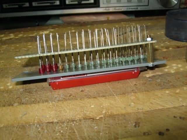
Look at the photo attached to show the variable resistors adjusted for the replacement STKs.
I hope this comes in handy for people wanting to fix these amps.
Good luck,
Luke
I have had a mission repairing an old Technics SUV4A amplifier and learnt a few handy tips along the way which I will share with you.
1/ If you need to replace the main amplifier ICs (a common fault in this amplifier - each one is an STK 8050), make absolutely sure that you first adjust both clamp voltage and idle current variable resistors to the full anticlockwise position. This is imperative as aftermarket STK8050s tend to operate at a much lower idle current and clamp voltage compared to the original ICs. If you don't do this before powering the amp up after fitting replacement ICs you will almost certainly blow both of them (I learnt this the hard way).
2. Follow the service manual to adjust clamp voltage on each channel (first ensuring R367 and R368 are turned full anticlockwise, along with R337 and R338) after 10 minutes warm up but DO NOT adjust it to 0.5mV!! Adjust it to about 0.1-0.2mV max. You will find that this is only a very small movement up from full anticlockwise on R337 and R338.
3. To adjust idle current, don't bother measuring the mV with a multimeter - just move R367 and R368 a tiny fraction up from full anticlockwise.
4. Carry out voltage tests on the legs of IC303 to confirm it is working correctly. This chip is known to fail on this amp.
5. Check resistor R326 for open circuit. This can also fail on the amp. On the amp I repaired, it had two blown STKs, a blown IC303 and a burnt out R326.
6. Check the volume control for signs of a worn track. The amp I repaired had a worn volume control which caused nasty voltage spikes and a crackling sound in the test speakers.
7. The input selector switch can become worn which can manifest itself with sound only coming out of one channel. Clean it with IPA and wiggle it a bit and it might restore it to almost normal operation.
8. When replacing the STKs, I found it easiest to use a hot air re-work gun with a fine nozzle, set to about 350 degrees C to melt the solder and gently pull the ICs away from the board.
Look at the photo attached to show the variable resistors adjusted for the replacement STKs.
I hope this comes in handy for people wanting to fix these amps.
Good luck,
Luke
Attachments
reality facts :
1) your IC is probably fake
2) your tuning procedure sucks big time (Tech dudes like to measure things according to the service manual, diyaudio ppl even worst ) But then this pointless when the IC is fake it will fail no matter if the bias is high or low ....
3) there was nothing told about the mains voltage settings This amplifier could be easily set up in the past for 220 now days we have 240 ...The few extra volts will be a stress to a normal IC imagine in a fake one ..The few extra volts will also effect settings ...it could be easily mean that there is no effective area in the trimmer
4) There is no comments about the capacitors.SU-V 4 come in 2 eras of capacitors the one was Nichicon ( black ) and the other was Mitsubishi (light blue ) In both cases capacitors are probably gone but for the misubishi things was far worst in most Technics machines today while capacitors will look like green salad down under .
Regards
Sakis
Yeah - the ICs are copies and definitely not genuine. In fact, I am not sure if you can actually get genuine STK 8050s made by Sanyo anymore.
I agree that this is not a perfect method but with so many copy STK 8050s around, it may well help others to not break their replacement STKs when following the service manual.
I checked the power caps with my ESR meter and according to that, they were OK.
I agree that this is not a perfect method but with so many copy STK 8050s around, it may well help others to not break their replacement STKs when following the service manual.
I checked the power caps with my ESR meter and according to that, they were OK.
Aha - now I remember what you said earlier about those small caps. I tested them also using my ESR meter. About 4 of them were close to their ESR limit - others were well below.
If money was no object for my friend I would most definitely replace the small caps on the board. In fact, he may well want to do that in the next few months. If it were my amplifier I would certainly re-cap the board. The amp had previously been in an attic in its broken state for well over 10 years.
If money was no object for my friend I would most definitely replace the small caps on the board. In fact, he may well want to do that in the next few months. If it were my amplifier I would certainly re-cap the board. The amp had previously been in an attic in its broken state for well over 10 years.
The problem with STK8050 is this:
1. The original parts will fail, even with light use. It seems Sanyo made a mistake and let this slip through to production without proper quality control. It's obvious why it was never used again after this.
2. There are only fakes available, and like the originals, these parts will fail, even with light use. Much lighter use.
Solution to all future readers of this post: do not waste your time with this amp. It is simply a flawed, improperly made product. Many have tried to repair it, and all have failed. It cannot be done right. You'll have to resort to running it under-biased like this, which is terrible for fidelity, and isn't even guaranteed to work in the long run. Either go full DIY on it (all-new everything, because it uses complex intertwined circuitry), or throw it away. You can't even strip it for parts because it only uses proprietary stuff not found in anything else.
Only once have I given up on repairing an amplifier. This is the one.
Last edited:
I dont know where you get your information from .....
At east electronics we repair amplifiers since 2010 we have electronic data base with every amplifier registered inside .
Since 2010 we have been repairing in total 19 amplifiers that are based in 8050 circuits and only one of them had output problems ...
Remember Greece is a small country
At east electronics we repair amplifiers since 2010 we have electronic data base with every amplifier registered inside .
Since 2010 we have been repairing in total 19 amplifiers that are based in 8050 circuits and only one of them had output problems ...
Remember Greece is a small country
Follow the website link
TECHNICS SU-V4A FULL Modifiye : Projeleriniz - Sayfa 8 - DIY Audio Türkiye Forum
https://www.youtube.com/watch?v=OICtpz1bREQ
TECHNICS SU-V4A FULL Modifiye : Projeleriniz - Sayfa 8 - DIY Audio Türkiye Forum
https://www.youtube.com/watch?v=OICtpz1bREQ
An externally hosted image should be here but it was not working when we last tested it.
An externally hosted image should be here but it was not working when we last tested it.
An externally hosted image should be here but it was not working when we last tested it.
An externally hosted image should be here but it was not working when we last tested it.
An externally hosted image should be here but it was not working when we last tested it.
An externally hosted image should be here but it was not working when we last tested it.
An externally hosted image should be here but it was not working when we last tested it.
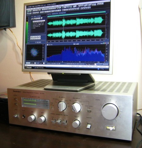
NEUTRIK test results came out as expected.
Although seen in preset 2dB common errors like these have already been corrected with Neutrik is normal.
The noise level was measured at -62 max volume level. Although the overall value created by the transformer should be -65 H. This is takabbül 102 dB dynamic range of 40dB to the overall amplifier gain factor.
The max level (30W output and tone controls defeat) distortion is measured as follows.
THD + N
30Hz 0.5%
250Hz 0.2%
500Hz 0.1%
1kHz 0.1%
5 kHz to 0.1%
10kHz 0.2%
20kHz 0.3%
The measured values for 1W output power of 465 NGOs are almost equivalent to that given in the general catalog. 0.08%
+ 3dB stop distortion measured for 10% overload. It complies with basic standards.
The frequency characteristics were measured only between 10Hz to 30kHz +/- 2dB skew.
Follow the website link
TECHNICS SU-V4A FULL Modifiye : Projeleriniz - Sayfa 8 - DIY Audio Türkiye Forum
https://www.youtube.com/watch?v=OICtpz1bREQ
An externally hosted image should be here but it was not working when we last tested it.
An externally hosted image should be here but it was not working when we last tested it.
An externally hosted image should be here but it was not working when we last tested it.
An externally hosted image should be here but it was not working when we last tested it.
An externally hosted image should be here but it was not working when we last tested it.
An externally hosted image should be here but it was not working when we last tested it.
An externally hosted image should be here but it was not working when we last tested it.
An externally hosted image should be here but it was not working when we last tested it.
An externally hosted image should be here but it was not working when we last tested it.
hola tambien tengo problemas con stk8050 muy buenos consejos amigo ya qufe he quemado varios remplazos gracias
Translated by moderation,
Hi also I have problems with stk8050 very good friend advice already qufe I have burned several replacements thanks
Translated by moderation,
Hi also I have problems with stk8050 very good friend advice already qufe I have burned several replacements thanks
Last edited by a moderator:
Tienes que renunciar a todo STK8050 existentes están diseñados de forma incorrecta, errónea o falsa. No puedes hacer nada. Acaba de lanzar el amplificador en la basura.
Translated by moderation,
You have to give up all STK8050 existing are designed in a way incorrect, erroneous or false. You can not do anything. It has just launched the amplifier in the trash.
Translated by moderation,
You have to give up all STK8050 existing are designed in a way incorrect, erroneous or false. You can not do anything. It has just launched the amplifier in the trash.

.bmp)
GENERAL RULES:
1 DISTORTION (Distortion) ratio.
2 NOISE (Noise) factor
3 FREQEN Frequency Response characteristic. (Depending on the power band)
As these basic rules studied three very large extent, in line with the questions of friends who questions will be examined in more detail from time to time.
1 DISTORTION: Each amplifier can distort the shape of a little upgrading, though a sine wave signal. DISTORTION This incident (failure) is called. Corruption is generally divided into two parts.
a) = IMD (Inter Modulation Distortion)
b) The THD (Total Harmonic Distortion)
2 NOISE: the increase in the proportion of each amplifier can amplify the sound signal unwanted signals. This raising of unwanted signal noise (noise) is called factor. The main factors for the noise factor, particularly GROUNDING rules, including ample supply circuit characteristics and the design factors.
3 FREQUENCY CHARACTERISTICS: Increase of the frequency of the desired sine signals to an amplifier, a minimum level should be max. frequency is called frequency characteristics of the section up to. The audio frequency is specified in the technical literature on the value of 20Hz to 20kHz skin.
The STK465 schemes mentioned as examples and photographs of some construction.
An externally hosted image should be here but it was not working when we last tested it.
An externally hosted image should be here but it was not working when we last tested it.
An externally hosted image should be here but it was not working when we last tested it.
An externally hosted image should be here but it was not working when we last tested it.
An externally hosted image should be here but it was not working when we last tested it.
An externally hosted image should be here but it was not working when we last tested it.
Designed and montage Mr_YAMYAM
AMPL?F?KATÖR'ler, tasar?m ve teknik anlat?mlar. (TARTI?MA)
An externally hosted image should be here but it was not working when we last tested it.
AMPL?F?KATÖR'ler, tasar?m ve teknik anlat?mlar. (TARTI?MA)
Last edited:
- Status
- This old topic is closed. If you want to reopen this topic, contact a moderator using the "Report Post" button.
- Home
- Amplifiers
- Solid State
- Helpful tips for repairing Technics SUV4A amplifier