Hello,
Is it hard to build or prototype a headphone amp nowadays, even for a starter like me ?
Few clicks and tricks with the Google and you got your access to hundreds of amplifier circuits.
I followed the last step and picked a few from diyaudio and some off google search.
Tested them with:
1. ATH-AD900 Blue Metal Closed 40R headphone Cans. They do not produce these anymore.
2. AKG K518LE ~32-40R impedance portable headphones
While cooking them on the breadboard i realized, that there is something wrong with all the circuits i have build so far:
For a brief moments, when testing HPA-s i could detect tonal balance change when volume is rised slowly from 0 to 100%. For example JLH was one of them who sounded differently on 10% volume vs 50% volume.
I then came to a conclusion that one should not push BJT-s quiesent current too high... it could be the reason why music tones are becoming so variable
My favorites:
Well, it was quite fun and easy TBH to construct, test and experiment... but now straight to the point:
All these amplifiers were OK sounding into AKG headphones... but they all failed hard into Audio Technica headset... More or less, but failing to produce clean sound. @ around 0.3 - 0.4V input voltage into any kind HPA gain stage.
It feels like AKG damps all the trash while Technics passes everything that amp is capable of (all that harshness, overshoots on middle tones and so on).
Using 3 different computer soundcards starting from my favorite:
There is a product called Creative X-FI HD USB soundcard that could drive these technics into heaven... with that DAC/Headamp the bass is very accurate and tight, most important... they produce drums and slam like a real speaker....clean sound from any audio coding format "i couldnt even tell the difference between FLAC or good MP3" lol..
Is there something missing from the circuits pointed out ? Somekind of crossfeed, filtering to smoothen/match the sound to the particular headphones ?
Its a suprise to me that ppl who have build these amplifier circuits are reporting good results lol.... maybe with a DAC, then it can be adapted to make AMP circuits sound good...
But with stock integrated soundcards its a NO GO...
Is it hard to build or prototype a headphone amp nowadays, even for a starter like me ?
Few clicks and tricks with the Google and you got your access to hundreds of amplifier circuits.
I followed the last step and picked a few from diyaudio and some off google search.
Tested them with:
1. ATH-AD900 Blue Metal Closed 40R headphone Cans. They do not produce these anymore.
2. AKG K518LE ~32-40R impedance portable headphones
While cooking them on the breadboard i realized, that there is something wrong with all the circuits i have build so far:
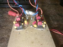
1. Desktop Sapphire Amplifier from diy audio – This is the circuit that lasted for a very long on the breadboard. Build 2 channels for stereo. Listened to the original parts configuration and as modified. As „modified“ i mean using different BJT-s in the same topology. BC337/BC327/BD137/138/139/140/TIP41C/TIP42C as output pairs, in the CSS and drivers particularly all BC series BJTs.
Gain stage – OPA2134, NE5532 and NE5534. Not quite there yet into Tehnics headphones.
RJM Audio - Sapphire headphone amplifier
Gain stage – OPA2134, NE5532 and NE5534. Not quite there yet into Tehnics headphones.
RJM Audio - Sapphire headphone amplifier
2. JLH single ended circuit – 2 of them for stereo, made them really small and compact. There was nothing to try different in terms of BJT-s, it played cute well allready(exept changing feedback values and output series resistors). It had its own tonal balance (new strange piano notes ) and was a bit slow in music. Best imaging and background compared to all HPA-s circuits i tested. I also liked the current and offset adjustment on the go.Not far from what i was expecting it to sound into Tehnics headphones.
FREE JLH 2005 Class A Amplifier PCB - Boards | Kits | Components | Modules | Tools
) and was a bit slow in music. Best imaging and background compared to all HPA-s circuits i tested. I also liked the current and offset adjustment on the go.Not far from what i was expecting it to sound into Tehnics headphones.FREE JLH 2005 Class A Amplifier PCB - Boards | Kits | Components | Modules | Tools
3. SC 2005 headphone amplifier – 1 channel only and pending. Seems like this configuration is comparable to Sapphire Desktop amp. Nothing new in here.
http://www.circuitdiagramworld.com/...tereo_headphone_amplifier_circuit_diagram.jpg
http://www.circuitdiagramworld.com/...tereo_headphone_amplifier_circuit_diagram.jpg
For a brief moments, when testing HPA-s i could detect tonal balance change when volume is rised slowly from 0 to 100%. For example JLH was one of them who sounded differently on 10% volume vs 50% volume.
I then came to a conclusion that one should not push BJT-s quiesent current too high... it could be the reason why music tones are becoming so variable
4. Opamps only - 1 channel only, different kind of circuit topologys, inverting and non-inverting configurations in unity/gain stages followed by unity gain non-inverting buffers:
http://www.diyaudio.com/forums/headphone-systems/271062-headphone-power-buffer.html
http://www.diyaudio.com/forums/headphone-systems/271062-headphone-power-buffer.html
My favorites:
IMO, with opamps... its easier, more fun and in overall better results @ sound and stability.1) I liked it the most: NE5534 as non-inverting input gain stage(gain ~1), output biased into class A(2 transistors,2 resistors), followed by 4 OPA134 buffers(2 chips).
2) NE5532, both amps in that chip are used as inverting amplifiers, last 5532 amp output on the same chp is biased to Class A with 2 „Transfer resistors“ and 2 resistors. Basically this circuit with reduced gain: ??????? ????????? ??? ????????? OPA2134 as buffers(4x)<-----output offset is very low ~0.2mV
I tried this with OPA2134 as input stage and NE5532 as buffers...offset 0.6mV.
Most neutral sounding configuration so far.....
Well, it was quite fun and easy TBH to construct, test and experiment
... but now straight to the point:All these amplifiers were OK sounding into AKG headphones... but they all failed hard into Audio Technica headset... More or less, but failing to produce clean sound. @ around 0.3 - 0.4V input voltage into any kind HPA gain stage.
It feels like AKG damps all the trash while Technics passes everything that amp is capable of (all that harshness, overshoots on middle tones and so on).
Using 3 different computer soundcards starting from my favorite:
1. U9200 ESPRIMO (intergrated, but it sounds just wonderful with NAIM NAP-140 clone AMP, it clips with ATH-AD900 but low volumes are good(no bass tho) )
2. Creative SB570 SoundBlaster descrete ADD-ON PCI 32bit card (Harhsss sounding into ATH-AD900... very unpleasent sound....)
First i tought this card was best out of three until i got the NAIM AMP´s working properly
3. DELL SFF 780 intergrated rear output – awful into every headphones i tried there
2. Creative SB570 SoundBlaster descrete ADD-ON PCI 32bit card (Harhsss sounding into ATH-AD900... very unpleasent sound....)
First i tought this card was best out of three until i got the NAIM AMP´s working properly
3. DELL SFF 780 intergrated rear output – awful into every headphones i tried there
There is a product called Creative X-FI HD USB soundcard that could drive these technics into heaven... with that DAC/Headamp the bass is very accurate and tight, most important... they produce drums and slam like a real speaker....clean sound from any audio coding format "i couldnt even tell the difference between FLAC or good MP3" lol..
Is there something missing from the circuits pointed out ? Somekind of crossfeed, filtering to smoothen/match the sound to the particular headphones ?
Its a suprise to me that ppl who have build these amplifier circuits are reporting good results lol.... maybe with a DAC, then it can be adapted to make AMP circuits sound good...
But with stock integrated soundcards its a NO GO...
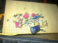
Attachments
You're using a PC with soundcard as a source? And what's the power supply you have to feed your prototypes?
Could be you have a common-mode noise problem originating from the PC's switched-mode supply. That could easily be the reason for the change in tonality as the volume control is moved.
Could be you have a common-mode noise problem originating from the PC's switched-mode supply. That could easily be the reason for the change in tonality as the volume control is moved.
Is it hard to build or prototype a headphone amp nowadays, even for a starter like me ?
My guess is that you'd be better off with a really good pair of headphones, used with the Marsh amplifier.
http://www.diyaudio.com/forums/headphone-systems/211394-marsh-headphone-amp-linear-audio.html
No, desktop speaker amp works perfectly with these sources, never had a problem with a "piano note´s variation" Its flat from 0 to 100%.
I have a regulated LM317AT&337AT PSU with right esr caps on the outputs.
But i use mainly homemade regulated PSU 0-30V/0-30V each 5 AMPS, two units forming split PSU.
PSU change has nothing to do with unpleasant sound at the moment...
Opamp based prototypes does not have this effect, it was mainly with higher biased circuits, JLH was most noticed and sapphire amplifier when run @ higher bias.
Over my body... actually a better idea would be to buy the Creative X-FI HD USB and integrate it in my preamp case .. but thats last thing i wanna do...
Its flat from 0 to 100%.I have a regulated LM317AT&337AT PSU with right esr caps on the outputs.
But i use mainly homemade regulated PSU 0-30V/0-30V each 5 AMPS, two units forming split PSU.
PSU change has nothing to do with unpleasant sound at the moment...
That could easily be the reason for the change in tonality as the volume control is moved.
Opamp based prototypes does not have this effect, it was mainly with higher biased circuits, JLH was most noticed and sapphire amplifier when run @ higher bias.
My guess is that you'd be better off with a really good pair of headphones, used with the Marsh amplifier.
http://www.diyaudio.com/forums/headp...ear-audio.html
Over my body
... actually a better idea would be to buy the Creative X-FI HD USB and integrate it in my preamp case .. but thats last thing i wanna do...Prototypes need tweaking. Layout counts. If you're stuck with a bad layout because of packaging constraints, then there are ways of mitigating it. Isolation resistors between stages is often all you need to compensate.
Grounding counts. There's a member here, Tom, who has a website about "engineering done right", with an article explaining grounding techniques. Read and understand it. If you don't do the grounds right, then the very best circuit can perform poorly.
I prototyped the JLH circuit a long time ago with 100% parts I had on hand and only had to change one resistor to make it work. It was so good that I almost built a version, but I ended up stuffing a "prototype" using the LME49600 into a case I had on hand. That was a year and a half ago and I'm still happy.
You can make a lot of circuits work well if you follow good grounding techniques.
BTW, i was using STAR grounding techniques.
The TEXAS ACTIVE VOLUME CONTROL i have build also uses Starground(components are extremly close to chips too)
and it works nice as a preamp for my main amplifier.
Okey, in near future, i will try all the circuits i have left (SC 2005 amp, Opamp based amp)
with different grounding topologies, series VCC-/VCC+ resistors with OPAMP gain-stages.
Build another MINI(LM3xx) split regulated PSU, and use separately for a buffer/outputs stages.
I somehow belive, that something needs to be done on the input of a gainstage.
OR if using 2 opamps on the input, then between them, A FILTER to lower some unpleasent frequency.
If I may suggest - toss the LM317. It's not a suitable match for the LM337. See the thread, around post 248 of - Another look at the LM317 and LM337 regulators
In that set of threads John Bau did a lot of work figuring out how to achieve a flat impedance across the audio band. If you're using the data sheets, the sound will be bad. Either go with LT1083/LT1085 regulators, bypass the adjust with 330 uF, decouple the regulator's output with 20 mOhms, keep the output cap to approx. 600 uF bypassed with 0.1uF cog/npo or polyproplyene to feed the headphone amp.
Or use the Jung-Didden SuperRegs.
As to opamps, try the AD797 for monolithic. Or build a pair of Jensen JE-918 discrete and feed them with +/-15 Vdc. Documentation can be found on Sam Groner's Audio web site and the kit page at WhistleRock Audio, which no longer sell the kits.
Sam Groner also show a headphone amp based on the SG-DOA-1 in that documentation. But, use the SG-SOA-2 discrete op amp which is available from diypartssupply.com.
Last edited:
BTW, i was using STAR grounding techniques.
I couldn't find the direct link, but browse this website. Neurochrome Audio: Precision high performance audio circuits for the DIY market. The principles discussed here are applicable to headphone amp design and construction.
I use a "modified" star ground for my audio circuits. Tom discusses this somewhere
and it's worth understanding, because it works.The TEXAS ACTIVE VOLUME CONTROL i have build also uses Starground(components are extremly close to chips too)
and it works nice as a preamp for my main amplifier.
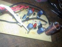
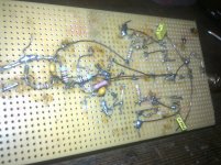
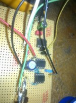
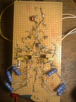
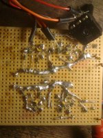
If you can make a circuit like this work, then you can make a headphone amp circuit work too. It is really difficult to determine what's wrong by looking at your pics because your prototype is extremely messy. I'm not saying that messy can't work, but it's poor practice and harder to troubleshoot. Layout counts!
I somehow belive, that something needs to be done on the input of a gainstage.
Like what? Buffers and proper input/feedback grounding cover most input stage problems, but often there is a simpler solution than buffering. Buffering can make some circuits work a whole lot better sometimes, though.Good luck though, and I hope your solution is a simple one.
disfunctionalshadow
Isnt this material is meant for a high-precision audio ? First i have to fix the main problem and then continue tweaking to the Highest-END
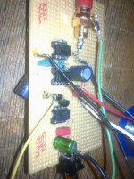
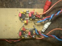
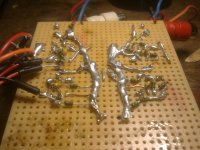
It does! I have reviewed and studied lots of Texas PDF´sLayout counts!
on layouts and chip bypass/decoupling.For example please see photos of Texas, it is finished and waiting for headphone amp.
Like what?
Maybe a ferrite bead...or a choke...and between gain stages some filtering throught crossfeed ?
And why AKG´s are OK with all the amps i have tried and Audio Technics are TOILET in all situations.... ?
Forexample.. i set the gain ~1.5 on the amp input stage.
I then turn the music on and start rising a volume from 0 - 20% throught a computer
, it playes well with Technics too.Then i crank up a bit more, around 40%, i feel bass coming up with everything else as natural. Then i switch the songs and start to detect something that shouldn´t be in there...Mostly it is described as "overshoot" on notes...
Finally, investigation goes further with the volume up to 60% and thats the point where "overshoot" are cutting into you eardrums.
By playing all kind of frequencies separately... the overshoot appear @ 1Khz-2Khz. It is disturbing... AND AKG´s are capable of damping that range
...But Audio Technics not..
It can be that These phones are too sensitive in that range... and i am asking for help to match constructed amps to these phones
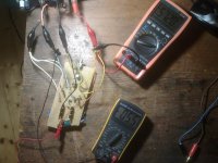
YES (7Mhz, USSR, Analog with green line)Do you have an oscilloscope?
Do i know how to use it ? NOt much... but i do check outputs for oscillations @ different divisions down to 5mV.
Dont know how. @ school i have sinewave generators and used it to checkDid you try a sine wave load test? Clipping stability test ?
"Texas TIDU034" with different kind of loads.
Attachments
I see. So the circuit works but not how you want it to work.
Just an observation - I've found that when you build a super low distortion, high resolution headphone amplifier, that you start to hear every little flaw in your equipment. All of a sudden you realize that your CD player is deficient, the mix on one of your favorite CDs is terrible and you never noticed, etc. However a low output impedance headphone amplifier (low impedance over the whole audio band) will make virtually all low impedance, high efficiency headphones that are typical today sound better - some a lot better. Older headphones from yesteryear might need a different solution.
Just an observation - I've found that when you build a super low distortion, high resolution headphone amplifier, that you start to hear every little flaw in your equipment. All of a sudden you realize that your CD player is deficient, the mix on one of your favorite CDs is terrible and you never noticed, etc. However a low output impedance headphone amplifier (low impedance over the whole audio band) will make virtually all low impedance, high efficiency headphones that are typical today sound better - some a lot better. Older headphones from yesteryear might need a different solution.
Some headphones, especially older models, sound better with a series resistor. Some were designed to work with series resistors and their frequency response is flat only with this series resistor, Typical industry standard was 150-600 ohms but you can certainly try other values (try lower values) and see if it fixes your sound,
Some low impedance headphones might sound better with a small series resistor (certainly under 30 ohms). You can only try.
Some low impedance headphones might sound better with a small series resistor (certainly under 30 ohms). You can only try.
Typical industry standard was 150-600 ohms but you can certainly try other values (try lower values) and see if it fixes your sound,
Some low impedance headphones might sound better with a small series resistor (certainly under 30 ohms). You can only try.
I will try this then, post back my results after. I have some Potentiometer type Selectors laying around from 80's amplifiers, so i can make a 3-4 step switch with different resistances. Thanks for the Idea
PS. Shouldn't the output series resistor mess up amplifiers damping factor ? I read that somewhere on the NET, the lower the output impedance, the better control over the headphones(bass and low frequency region mostly) ???
Last edited:
I will try this then, post back my results after. I have some Potentiometer type Selectors laying around from 80's amplifiers, so i can make a 3-4 step switch with different resistances. Thanks for the Idea
It's cool, bro. You're building it, so you can give it the custom features you want. And you won't be the first guy to put switched resistors on the output either.
I read it on the web so it must be true.PS. Shouldn't the output series resistor mess up amplifiers damping factor ? I read that somewhere on the NET, the lower the output impedance, the better control over the headphones(bass and low frequency region mostly) ???
Actually, it is true. And changing the damping factor will potentially change the sound with some phones, which is really the point of this feature.
And it will potentially change the frequency response too, which is also the point of this procedure. It can potentially change it for the better, especially with older "vintage" phones that were designed to perform to specification with the resistor in series. It can accentuate the bass and/or smooth out peaks.
Finally, damping is not as critical with headphones as it is with speakers, in general. And in fact, some older speakers of yesteryear worked fine with very little damping. Old tube amps with no global feedback usually had very poor damping factor, and the old speakers were typically high Q and mounted in an open baffle.
This is really a subjective exercise, and the results might be subtle or even unsatisfactory. All you can do is try, so get a little collection of resistors together. Let us know how it works.
Last edited:
Jesus christ, Magic
I hooked UP a 200ohm potentiometer to a SC 2005 amp output, 1 channel
Sound is softer after 50R resistance on the output and becomes a little better when increasing
About 68R on the output seems reasonable.
Gainstage has been raised from 1 to 4x.
Soundcard input max 0.7-0.8V.
With 100% volume, there is no unpleasant overshoots anymore and bass is still there....
I will keep you updated with 2 channel amps in near future(Y)
Jesus christ, Magic
No, it's physics.
The frequency response curve has likely been altered for the better. Maybe a peak has been reduced, maybe a rising response has been flattened.
Perhaps the "overshoots" you perceived were peaks or resonances, or an unpleasant tonal balance. If your phones have an uneven impedance vs frequency curve, then a series resistance will certainly affect the frequency response.
This is a subjective exercise, but it can be objectively observed. This is also a very common procedure among DIYers. It works!
The "standard" source impedance is 120R, IEC 61938 (1996),
(for amplifier headphone outputs), but that is pretty useless
for modern low voltage portable devices and their headphones.
Anyone who has tried to run modern, low impedance headphones from a "classic" receiver headphone jack, knows this. It has never sounded acceptable to me. Most modern headphones, even some of the nicer ones, are designed to run from mobile devices. These devices typically have low output impedance and limited voltage swing. But a 32 ohm set of headphones isn't going to perform very well with a 120 ohm resistor in series with it; but a 600 ohm set of headphones usually will.
This is silly, but I am going to say it anywayJesus christ, Magic
I hooked UP a 200ohm potentiometer to a SC 2005 amp output, 1 channel
Sound is softer after 50R resistance on the output and becomes a little better when increasing
About 68R on the output seems reasonable.
Gainstage has been raised from 1 to 4x.
Soundcard input max 0.7-0.8V.
With 100% volume, there is no unpleasant overshoots anymore and bass is still there....
I will keep you updated with 2 channel amps in near future(Y)
Did you run the test with the HP working at the same sound pressure? The series resistor will now dissipate the power which was previously turned into sound by the HP.
Also, if your amp is not stable under large phase loads (capacitive - most likely - or inductive), the series resistor is going to bring back the phase of the load seen by the amp, towards lower values.
This is silly, but I am going to say it anyway
Did you run the test with the HP working at the same sound pressure? The series resistor will now dissipate the power which was previously turned into sound by the HP.
That should be obvious. I doubt it's a true A/B test, but that doesn't mean you can't tell it's working.
It's really a subjective exercise.Also, if your amp is not stable under large phase loads (capacitive - most likely - or inductive), the series resistor is going to bring back the phase of the load seen by the amp, towards lower values.
True.
But a 32 ohm set of headphones isn't going to perform very well with a 120 ohm resistor in series with it; but a 600 ohm set of headphones usually will.
I still can´t comment on quality of the sound/stage/bass response cuz of the mono.
Will do that soon.
Maybe, Audio Technics have very high damping factor and if HeadPhone Amp damping factor is also sky rocketing then the result = TOILET ???
100R resistor messes up with amp damp. factor ?? and in the end everyone is happy
Yes, i had to rise the gain to 4x to get the same pressure at high volumes.Did you run the test with the HP working at the same sound pressure? The series resistor will now dissipate the power which was previously turned into sound by the HP.
Series resistance is now 100R, i have them alot... and it suits very well.
I tried 100R with the opamp buffer stages too [ NE5534 as input gain (gain 3x), 3xOPA2134 as unity gain buffers].
SC 2005 amp seems more right with 100R in series compared to opamp setup...
I will decide tommorow, which schematic to use to make stereo.
Also, if your amp is not stable under large phase loads (capacitive - most likely - or inductive), the series resistor is going to bring back the phase of the load seen by the amp, towards lower values.
U mean that series resistance is making amps output more linear ?
- Status
- This old topic is closed. If you want to reopen this topic, contact a moderator using the "Report Post" button.
- Home
- Amplifiers
- Headphone Systems
- Amp matching to headphones